Brand:GE Model Number:JCPB800DT1WW Main Symptom:DIFFERENT TERMINALS What happens & when:
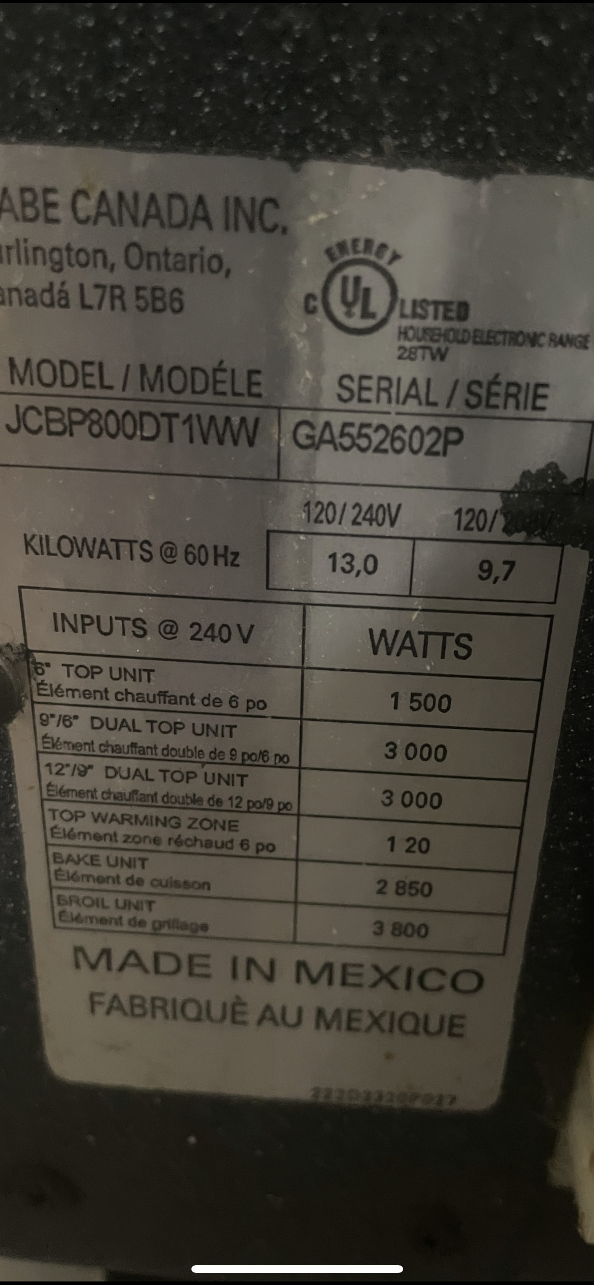
GE ELECTRIC STOVE MODEL #JCBP800DT1WW
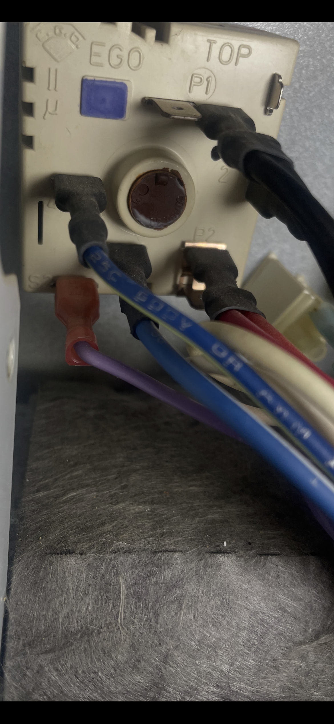
I NEED A NEW SWITCH #WB24T10058 FOR A 11 INCH DUAL BURNER. THE NEW SWITCH YOU HAVE AVAILABLE IS MISSING TERMINALS S1-S2-4A SO BEFORE I PURCHASE I WAS HOPING TO VERIFY NEW WIRING. I DID SOME RESEARCH AND FOUND OUT GE REDESIGNED THE NEW SWITCH TO PART NUMBER WG02F04019. THE LOGIC IS NOW DONE INTERNALLY IN THE NEW SITCH. BUT I STILL WILL HAVE EXTRA WIRES. MY OLD 10058 SWITCH IS AS FOLLOW
P1-DOUBLE BLACK WIRES
2-YELLOW
P2-DOUBLE RED
S1- IS EMPTY BUT P2 AND S1 ARE BRIDGED WITH A EXTERIOR JUMPER
4A- BLUE WIRE WITH WHITE STRIPE
S2- PURPLE WIRE
4- BUE WIRE WITH GREEN STRIPE
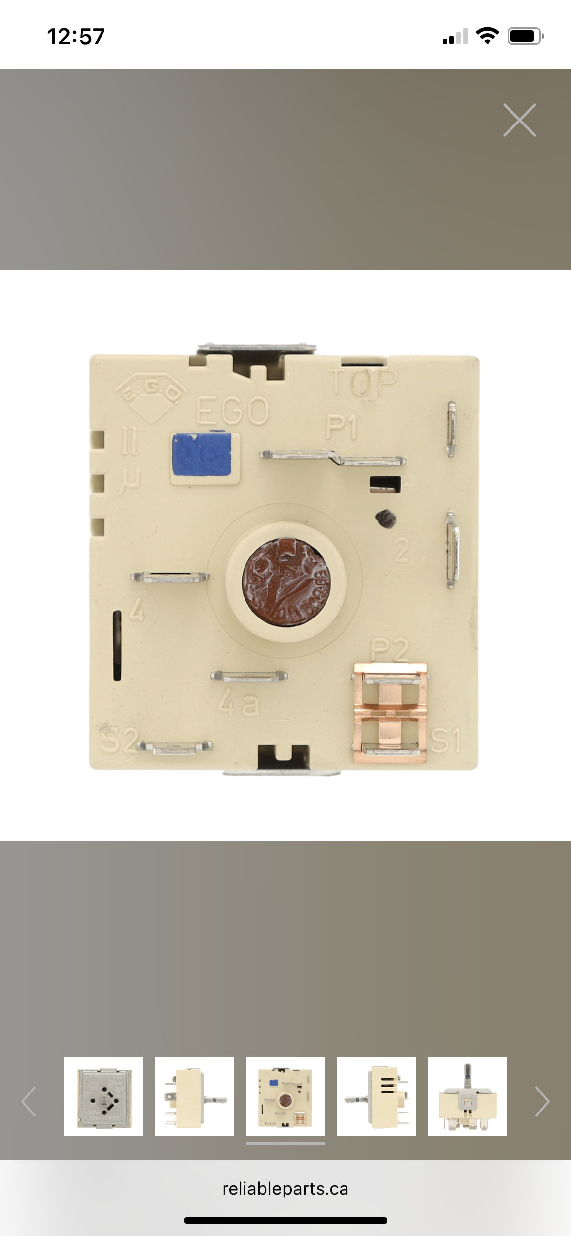
THE NEW SWITCH YOUR WEBSITE HAS #WB24T10058 HAS ONLY TERMINALS
P1
2
P2
PILOT
4
I WAS HOPING YOU CAN HELP MAKE SURE I HAVE CORRECT SWITCH AND HELP WITH THE NEW WIRING BEFORE I PURCHASE. THANK YOU
HI BIGBUCK. thank you for the reply. The wiring diagram is the correct one for my model. The WB00X7094pdf you sent i think is for the RR right rear and the LR left rear single burners. The original switch WB24T10058 that has now been replaced by WG02FO4019 is the RF right front 11 inch dual burner. Thats the diagram im looking for. The diagram you sent is exactly what im looking for but for the new switch. GE used to give them in the package with the new switch but not no more. You woudnt happen to have the new instruction wiring table just like the other one you sent but for the 11 inch dual RF burner OLD WB24T10058 to be replaced with NEW WG02FO4019 infinite switch. Thanks a million for all you help!!!
For GE JCBP800DT1WW, WG02F04019 is listed as the dual surface-element switch for this model.
The problem is that WG02F04019 is a redesigned switch, so the terminals do not correspond one-for-one with the original WB24T10058. I would not guess at the three leftover wires.
Your original switch wiring is:
Old WB24T10058 terminal
Wire
P1
Double Black
2
Yellow
P2
Double Red
S1
No harness wire; jumper from P2 → S1
4A
Blue/White
S2
Purple
4
Blue/Green
The new WG02F04019 has P1, P2, 2, 4 and PILOT, so simply moving wires according to terminal names leaves Blue/White, Purple and the old P2-S1 arrangement unresolved. That exact mismatch has also been documented for this model and replacement.
What I need to give you the exact hookup
Don’t connect power yet. Send me a clear picture of the back/terminal side of the new WG02F04019, preferably showing every terminal marking.
Once I can see the terminal layout, I can make you a simple table:
OLD TERMINAL → WIRE COLOR → NEW TERMINAL
and tell you exactly what happens to the Blue/White, Purple, and old jumper. With a 240-V surface control, I don’t want to make an assumption based solely on the replacement number. GE also states that the range’s wiring diagram/mini-manual is the authoritative wiring reference.
Yes — that picture confirms the WG02F04019 has these five usable terminals:
P1
2
P2
4
PILOT
It is the correct dual-element switch listed for JCBP800DT1WW, and it supersedes WB24T10058.
However, the photo does not resolve where the old 4A (blue/white) and S2 (purple) circuits are supposed to be transferred. The old switch used additional contacts that aren’t physically present on this EGO switch. The exact same wiring problem for this exact model/replacement has been documented, but the published discussion doesn’t yet contain GE’s conversion wiring table.
What we can safely establish
Old WB24T10058
Existing wire
New WG02F04019
P1
Double black
P1
2
Yellow
2
P2
Double red
P2
4
Blue/green
4
S1
Jumper from P2
Do not install jumper yet
4A
Blue/white
Need conversion instructions
S2
Purple
Need conversion instructions
—
—
PILOT needs correct assignment
I would not power the range with those last connections guessed. This switch handles 240 VAC / 13 A, so an incorrect connection can short L1/L2 or energize the wrong portion of the dual element.
The next thing I’d want is the JCBP800DT1WW wiring diagram/mini-manual. With that diagram I can trace purple and blue/white and give you the complete old terminal → new terminal conversion.
29-5711 GE JCBP800DT1WW Range Mini Manual.pdf
PDF
Yes — that mini-manual helps a lot. The important point is that this range uses current-sensitive surface switches, and GE specifically warns that the leads must be connected to their proper corresponding terminals. Reversing the line connections can damage one or more switches.
For the WG02F04019 switch in your picture, the markings translate to the GE diagram terminology like this:
New switch
GE diagram function
P1
L1 – incoming line
P2
L2 – incoming line
2
H1 – element output
4
H2 – element output
PILOT
Surface-unit ON indicator circuit
The mini-manual’s surface-switch diagram specifically shows L1, L2, H1, H2 and P/PILOT going to the surface unit.
Based on your original wiring
I would wire the new switch:
Existing wire
Old terminal
New WG02F04019
Double Black
P1
P1
Yellow
2
2
Double Red
P2
P2
Blue/Green
4
4
Pilot/indicator circuit
—
PILOT
But I would NOT put the purple or blue/white wires anywhere yet.
Those extra wires are associated with the old dual-circuit switching arrangement, and the uploaded GE diagram does not provide a conversion chart from the old 7-terminal switch to this 5-terminal EGO switch. That’s important because GE explicitly warns against incorrect surface-switch connections.
Also, do not automatically reinstall the old P2 → S1 jumper on the new switch.
If you can send me a picture of the old switch with all the wires still connected (or a good picture of its terminal side), I can trace the purple and blue/white wires against the schematic and determine whether WG02F04019 requires an adapter/jumper arrangement or whether we’re dealing with the wrong replacement configuration.
Also I ran this thru an untrusted source and he told me to put the purple-blue and green stripe-blue and white stripe wires all on terminal 4 using piggy back connectors.
So terminal
p1- double black (L2 feed wires)
2- blue (H2 lead)
P2- double red (L1 feed wires)
4- blue/green-blue/white-purple
GE moved all the dual element logic inside the new switch and terminal 4 is now the single combined output for 4-4A-S2
Pilot-empty
But I cannot trust this source ANY HELP WOULD BE GREATLY APPRECIATED
THANKS AGAIN
Those pictures help. The old switch layout is now clear, and the wiring shown matches the sketch:
Old switch terminal
Wire shown
P1
Black — two black leads on the connection
P2
Red — two red leads
2
Yellow/light-colored lead
4
Blue
4A
Blue/white
S2
Purple
S1
Jumper/circuit associated with P2
The important part is that this is not a simple terminal-for-terminal replacement with the 5-terminal WG02F04019. The old switch has separate S1/S2 and 4A contacts for selecting the two sections of the dual element. The replacement pictured earlier only gives us P1, P2, 2, 4 and PILOT.
GE’s mini-manual confirms that the dual controls select the large zone in one direction and the small zone in the other. It also specifically warns that these are current-sensitive controls and the leads must be connected correctly; reversed wiring can destroy switches.
So I would not connect the WG02F04019 yet based on the assumption that the extra purple and blue/white wires can simply be combined or abandoned.
I think we’ve found the real issue
The WG02F04019 shown earlier appears to be the wrong switch configuration for this particular dual burner circuit, unless GE supplied a separate conversion harness/instruction sheet with it.
Your original control requires seven functional terminal positions:
P1 – P2 – 2 – 4 – 4A – S1 – S2
The replacement only provides:
P1 – P2 – 2 – 4 – PILOT
That’s not just a different physical terminal arrangement. It’s missing the contacts needed to switch between the two heating zones.
The GE service information even says the replacement infinite switch should be a current-sensitive switch with the same wattage rating.
I would stop here rather than modify the wiring. At this point I’d verify the replacement part number against the exact burner position you’re replacing—left front or right front—because JCBP800DT1WW has dual controls in both positions, and they may not use the same switch.
Tell me which burner this switch controls — left front or right front — and I’ll nail down which switch configuration we need.
Well that sucks. I didn’t even notice it was made in Canada. I would think that it theoretically woks the same. Do they have different electrical up there lol.