Brand: samsung Model Number: Samsung WV60M9900AV/A5 Main Symptom: Stopping during wash What happens & when: usually first 5 mins but at different stages, Can restart might work for a few mins. i hear it draing at start fine then when filling water it stops and starts a few times. Top washer is working fine start to finish. I have replaced drain pump and checked hoses. Checked water inlet filters. Ran a calibration cycle and still have issue. Ran diagnostic sequence and was ok also.
Maybe control board? Thanks!
Error Code (if any): none just stops with time still on remaining can restart usually then stops again
Parts or tests already tried: replaced drain pump, inspected hoses. inlet filters and pressure. calibration
Photos / video link:
If you power the main washer on and press the Delay button until 17h is displayed, press and hold Start until AS is displayed, press the Smart Control button, then press Spin, does an error code appear in the display?
From what I can find, anything related to the upper washer would start with a 1 like this, while anything for the lower main washer would only start with a 1 for the water level error 1C. The error codes I can find relating to the ending C2 for the lower main washer are the following: 4C2 water supply error, 9C2 power error, BC2 switch error, and 8C2 Mems PBA error. If you try to get the display to show the segments where the 3 showed up, does it look like any of the LEDs will not illuminate at all?
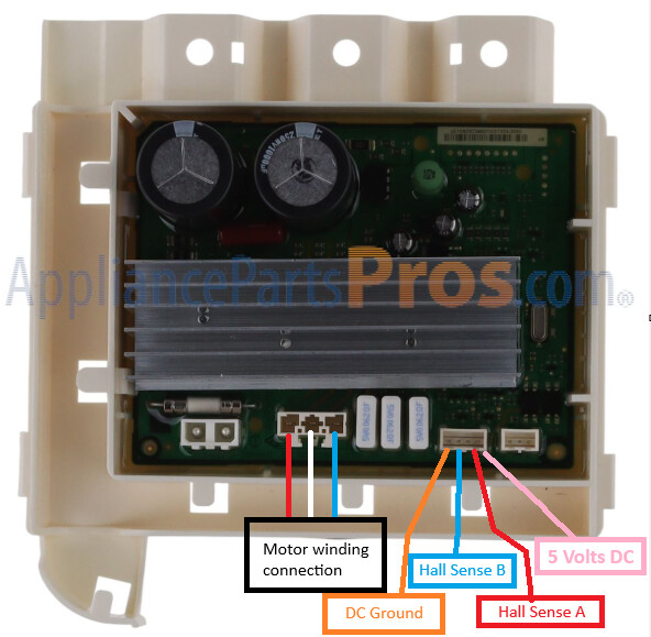
More than likely, the control is showing an error 3C with a sub code of 2, which could potentially mean an issue with the motor and hall sensor circuits. There are some checks that can be done to see what might be causing this. First, does the spin basket rotate freely by hand? Then with the power cord unplugged, remove the back access panel of the washer. The main control and the inverter will be located at the bottom. Separate the control covers from the control housing and rotate the controls so that they are facing upwards (housing facing down). The attached image can be used for connection and test point reference. There will be a large 3 wire connection on the inverter that goes to the motor windings. With a multimeter set to resistance, disconnect the wires from the inverter and test from the red wire to the blue wire, red wire to white wire, then blue wire to white wire. The resistance readings should all be very close to each other. The manufacturer’s information shows the resistance should be between 10-12 Ohms. If the resistance checks good, plug the wires back into the inverter. A voltage check will be the next test. Plug the power cord in and set the multimeter to Volts DC. With the black meter probe set into the orange wire, set the red probe into the pink wire. With the probes set, press the power on button and check the voltage reading. It should measure 5 Volts DC. If it does, move the red probe to the red wire. With the probes in place, rotate the spin basket. There should be a DC voltage reading. If I remember correctly, it will likely show something around 3 Volts DC. This same would be done after moving the red probe to the blue wire. Let me know what you find and we can go from there. Also, is there an REV number or a /## on the model tag?
It is good that it spins freely. This tells us there is not any drag created by the bearings. Depending on the testing results, this could be a motor, inverter, or control failure.