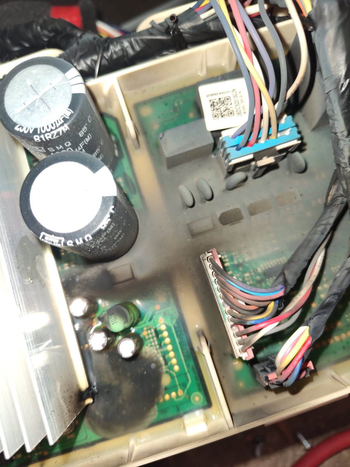
Brand: samsung Model Number: WF45M5500AP/A5 Main Symptom: 3C1 error code, will not start any cycles What happens & when: washer originally stopped working at all with no power, found burn mark on the main/inverter board on the bottom back of the washer inside, replaced those boards, made sure there was no burnt wires or connectors which there was notmnow I have power but now 3C1 error code shows ypll, when I try to start a cycle the drum will twitch or spin one or two times and then stop well the displays just shows a circle spinning meaning it’s “thinking”. It won’t start or complete a cycle. Help!
Error Code (if any): 3C1
Parts or tests already tried: replaced inverter/main board that fixed original no power issue
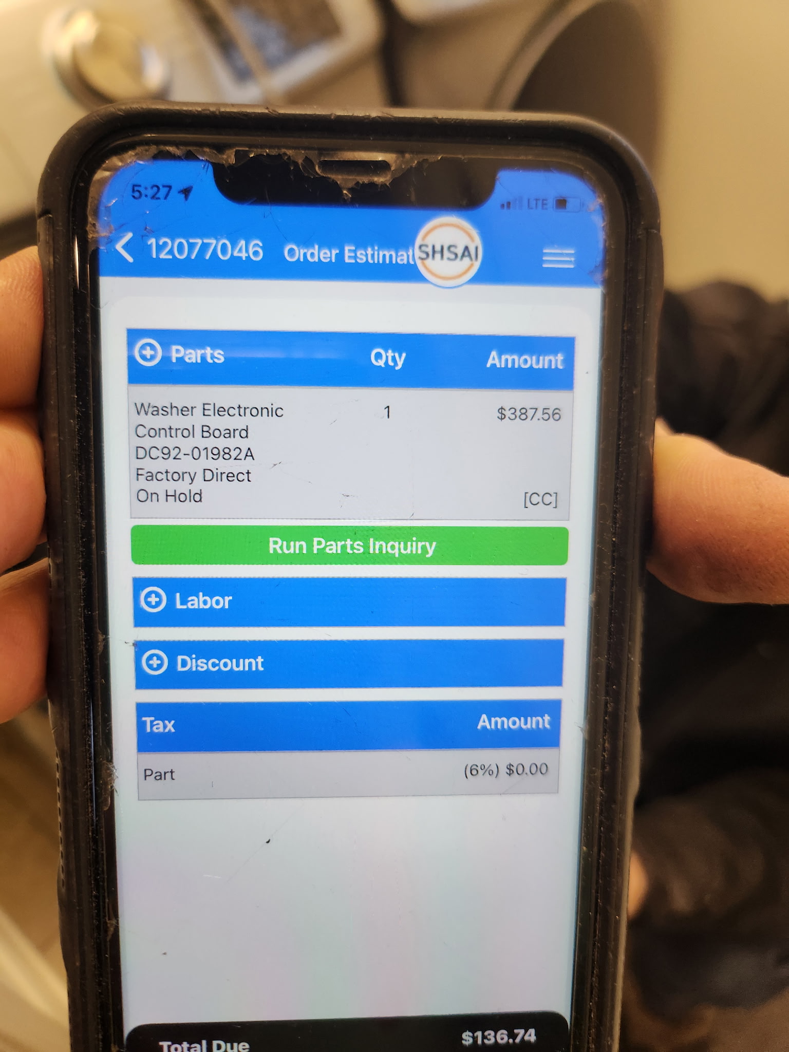
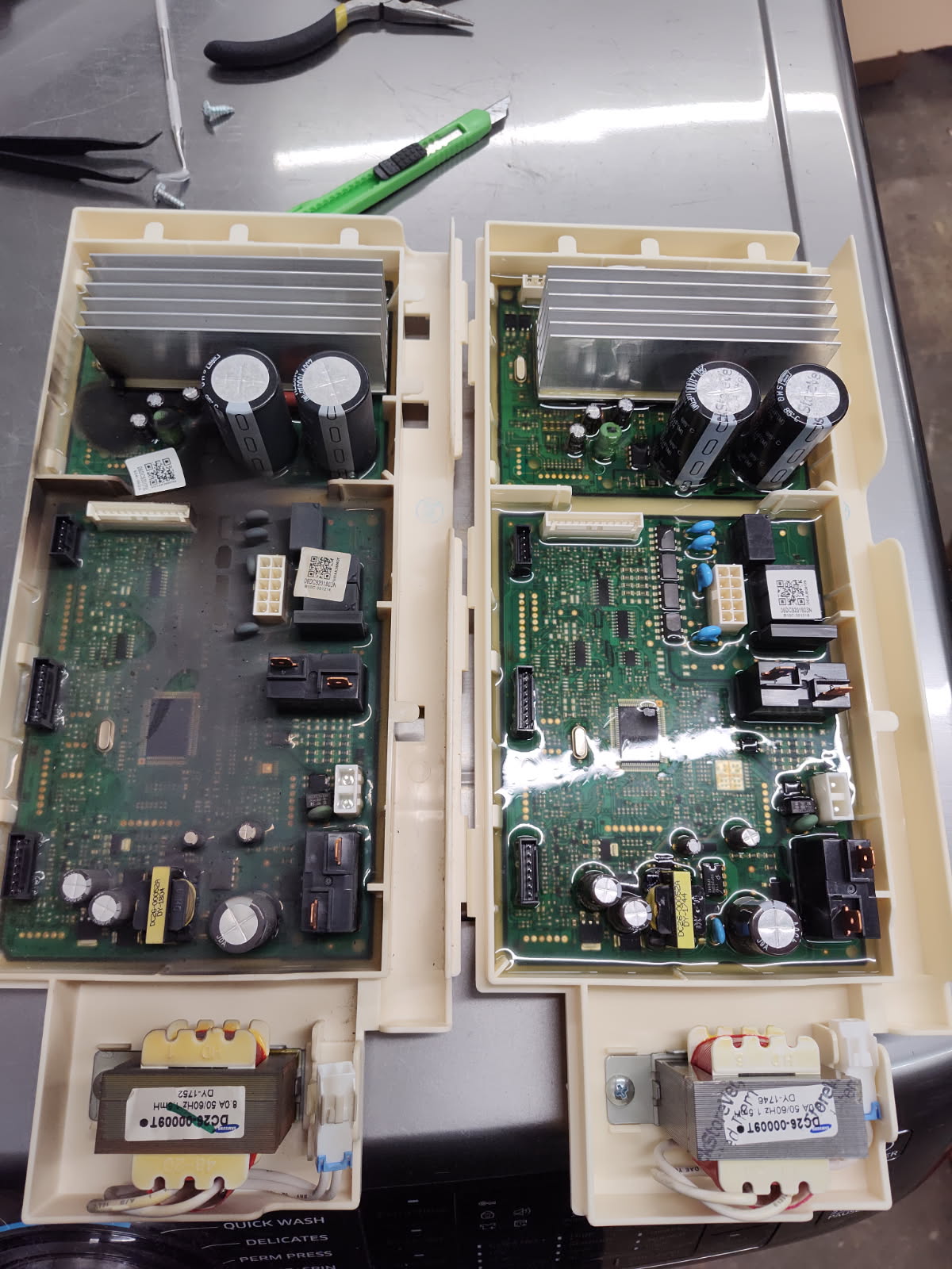
Photos / video link: control board part number, and pictures of the original burnt control board versus the replacement I installed..
There are a couple of checks that can help identify why this is happening. The first check would be identifying if the spin basket rotates freely by hand and if it wiggles around inside of the tub. Both the spin basket and tub should wiggle up and down, side to side, and diagonally at the same time with no change in spacing between the two. If that checks good, the next step would be unplugging the power cord and testing the stator for resistance after disconnecting the wires. When measuring from terminal to terminal, and testing each possible terminal set, there should be a resistance around 6 Ohms. Do these checks pass testing?
I will check those things tonight and report back. Pretty sure what you said about the drum is fine but I’ll check it anyways. This all started happening when the main board / inverter board burned up and can you clarify for me the inverter board and main board are all one component on this washer right? They are one piece in the same plastic cover on the bottom of the back of the washer? Thanks
It is correct that the main control and the inverter are in the same housing. The inverter board is the smaller one in the plastic housing in the picture that was provided.
Okay I just took the washer apart. Following your video on YouTube for a similar washer “Samsung Washer Not Spinning FIXED! 3C Error Code Solution” I took off the magnets for the motor and they were perfectly clean no damage or debris. Then I took off the stator and tested the three pin plug like shown in the video and every combo of pins was at 11.8-12.0 ohms. You said that the stator is supposed to be at 6.0 ohms. Is that cause for concern? They aren’t too far off and all of them have equal readings so I’m not sure if that is normal or notSamsung WF45M5500AP/A5
The next part of the video he said if all that checks out then the circuit board is bad but I replaced it with a used one that was “tested” from an online seller. Originally the washer had no power so replacing the circuit board restored power and let it turn on. But I’m wondering if the replacement board I got could be bad? Doing a visual test of course it didn’t have any abnormalities or burn marks like the original one had (original boards capacitor burned up). But I know just because there’s no visual signs doesn’t mean everything is fine. What are my next steps here? Stator bad? Thanks in advance!
From what I see in the manufacturer’s technical information, the windings should measure close to 6 Ohms. If the windings started to fail and increased in resistance, it can potentially cause the inverter to burn out like it did on the original. Here is what information I have on this error.
Thanks for the picture from the manufacturer. Yes I am getting 11.8 ohms at all the pins of the 3 pin stator plug. In regards to the second photo about the four pin Hall sensor the picture in the diagram you sent me my PCB control board does not look like that. I did probe out the 4-pin plug on the stator and I get readings between 0.8-2.9 ohms. But only on three of the pins. The pin on the four pin plug that is closest to the three pin plug I do not get any ohm reading when probing that PIN with other pins. Hope this makes sense. I did find a cheaper stator on eBay that I just ordered so I can test it when it arrives. First thing I will do when it arrives is test the ohms to see if there’s any difference from my original and then I’ll slap it in there and see what happens! Possibly the hall sensor could be the issue if I am getting weird readings like I stated?
It is possible that the RPS sensor may have caused issues. Since two of the wires are feedback wires, one wire is the voltage supply, and the last wire is a DC ground wire, I believe they should all have a reading when measured to each other. I could be wrong on this point though since voltage testing is the only method I use when testing the RPS sensor.
Well I did order a used stator from eBay for cheap so that I can at least do some testing with it.. first I will test the ohm values on the donor that I’m receiving to see if they are any different for my original. If I find that the new one has six ohms resistance then I can be pretty sure that my original is no good. It comes with the sensor as well so I will test it out when I receive it and I’ll follow back up on here! Thanks again!
Any answers if it’s the stator or the rotor position sensor who was defective ? I got the exact same problem on the exact same washer(WF45M5500AP/A5). I’ve replaced the board and got a 3C1 error with all the same readings he did.
Tornade90, thank you for your question. Was the original cause of failure a 3C1 issue or is the error code a recent development since changing out the control?
The inverter assembly burned on the same spots as Bcautoworks.
I’ve changed the assembly to the newest number DC92-01982A.
Power came back to normal on the washing machine but now the drum was not turning much, just a small jerking movement clockwise and countherclockwise and a 3C1 error when going in test mode.
I’ve had all the same numbers and resistance values as Bcautoworks.
Since he didnt gave a feedback and he said we was trying a DC31-00111A stator assembly. I’ve decided to try an assembly since I had only this close for pick up in a shop.
It was either the motor or the position sensor DC31-00098A because I’ve changed the whole assembly and ran the test mode and it passed right away. I did a calibration and its now working like a charm.
Resistance where all good on the motor windings, but something was off, there was a burning smell. I think its safer to change the whole assembly in this case, it might be the reason the control board burned.
Hey man, yes replacing the stator fixed the issue, but I believe it was the sensor on the stator what you call the rotor position sensor that was fried from the inverter board frying. Sorry I just saw the email that you replied or I would have got back to you sooner
So for anyone that is dealing with the same issue that comes to this forum thread and has the same model number washer with a burnt up board, the following steps to fix.
Replace board with newest revision or same part number as original
Test and if the drum isn’t spinning or acting erratic, then check resistance of stator to see if it’s within spec. If it’s still within spec it’s probably the rotor position sensor. Replace stator and rotor position sensor (it’s all one assembly).
Hope this helps someone in the future, it took me months of research to do it on my own and figure out the stator/rotor sensor was the issue. What kept throwing me off was that the new stator and my original had the same ohm reading. But I tried the new one anyway and boom! It worked. For the used board and used stator I was in it for around $220.
With the new stator testing the same and operating normally, it’s likely that the testing information in the tech sheet isn’t accurate for this design. More specifically, it may not be accounting for the fact that the reading is being taken across two windings in series, which will be measured by adding both resistances together, or doubling the expected reading in this case.