I purchased part number 74002666 (dual element) to replace existing element (inner coil not functioning). This was confirmed to be the correct part by your customer service. The part appears identical but the ceramic switch-head is different. The instructions included with the part recognizes that the ceramic switch-head of the replacement part may be different, and provides an alternative wiring. My problem is this…the wiring diagrams included with the new part only show 4 wires attached to the element. My original element had 5. The attached pdf shows the wiring diagram received with the new element. Note that the ceramic connector on the new element has a third tab just like my old element. If I put the 5th wire on the empty tab on the ceramic connector block, only the inner coil functions.
DUAL ELEMENT WIRING DIAGRAM.pdf (1.2 MB)
In what position is the “Coil size” switch on the control panel?
Gene.
Gene…
Only the center burner functions whether the switch is in the 6" or 9" position. I tried it both ways thinking I may have switched a wire when I installed the new element.
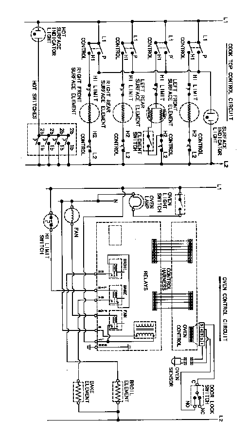
According to the wiring diagram the two wires from the infinite switch terminals “H1” & “H2” (outgoing power) should be connected:
“H1” through the limit switch to the common heat element terminal (middle part of both coils);
“H2” has two wires connected. One goes straight to the center coil terminal, supplying power to it as soon as the infinite switch turned “On”. The center coil is always “On”. The second wire goes through the “Coil size” switch on the control panel and connected to the outside coil, so when 9" size is chosen, it supplies power to the outside coils. At this time both coils are powered up.
I hope it helps.
Gene.
[QUOTE=Gene;158779]According to the wiring diagram the two wires from the infinite switch terminals “H1” & “H2” (outgoing power) should be connected:
“H1” through the limit switch to the common heat element terminal (middle part of both coils);
“H2” has two wires connected. One goes straight to the center coil terminal, supplying power to it as soon as the infinite switch turned “On”. The center coil is always “On”. The second wire goes through the “Coil size” switch on the control panel and connected to the outside coil, so when 9" size is chosen, it supplies power to the outside coils. At this time both coils are powered up.
I hope it helps.
Gene.[/QUOTE]
Hi Gene…not sure yet if this helps. I’ll have to take a closer look at the wiring diagram in your message. It is not the same as the wiring diagram that came with the new element…Jack