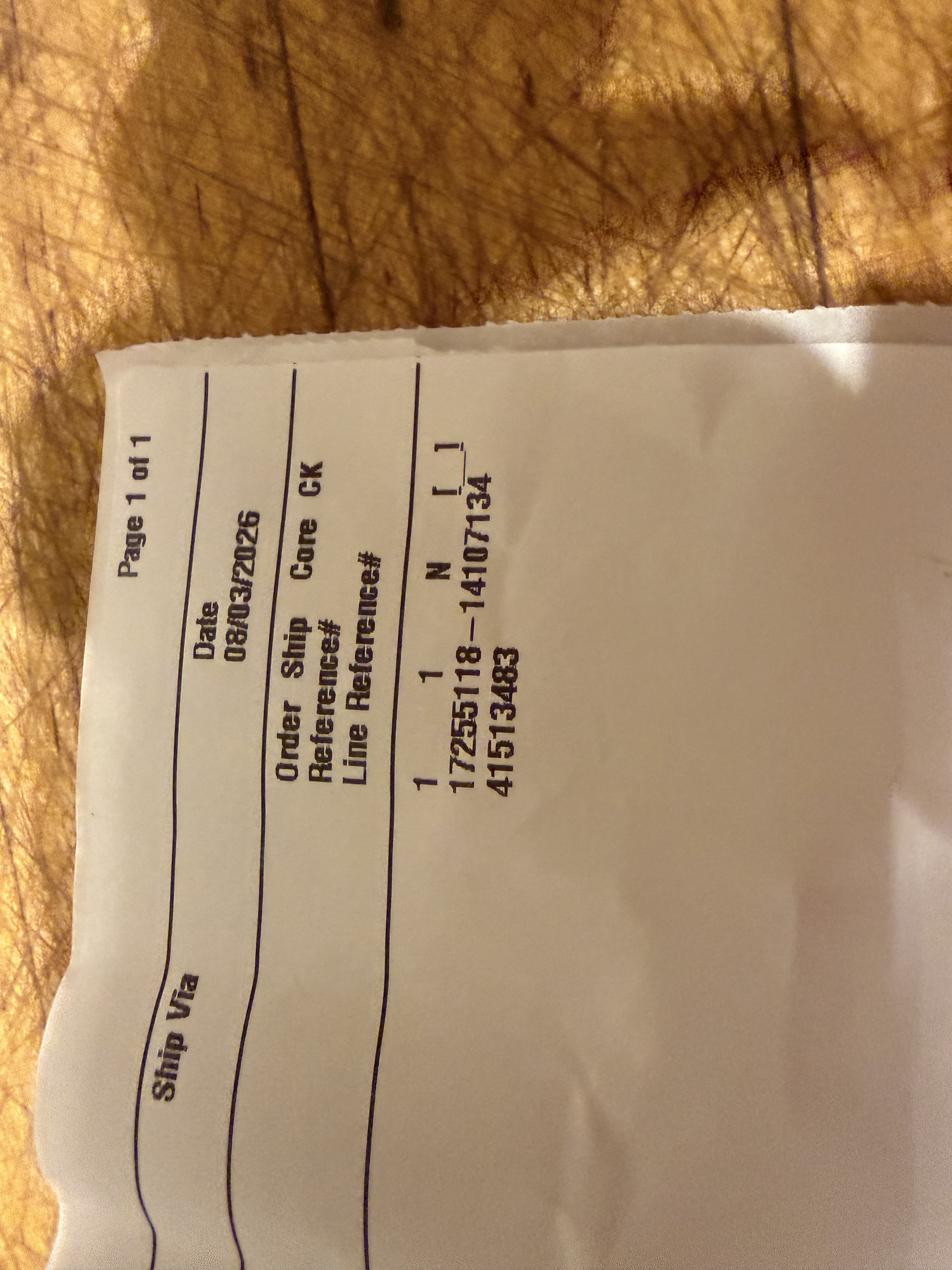
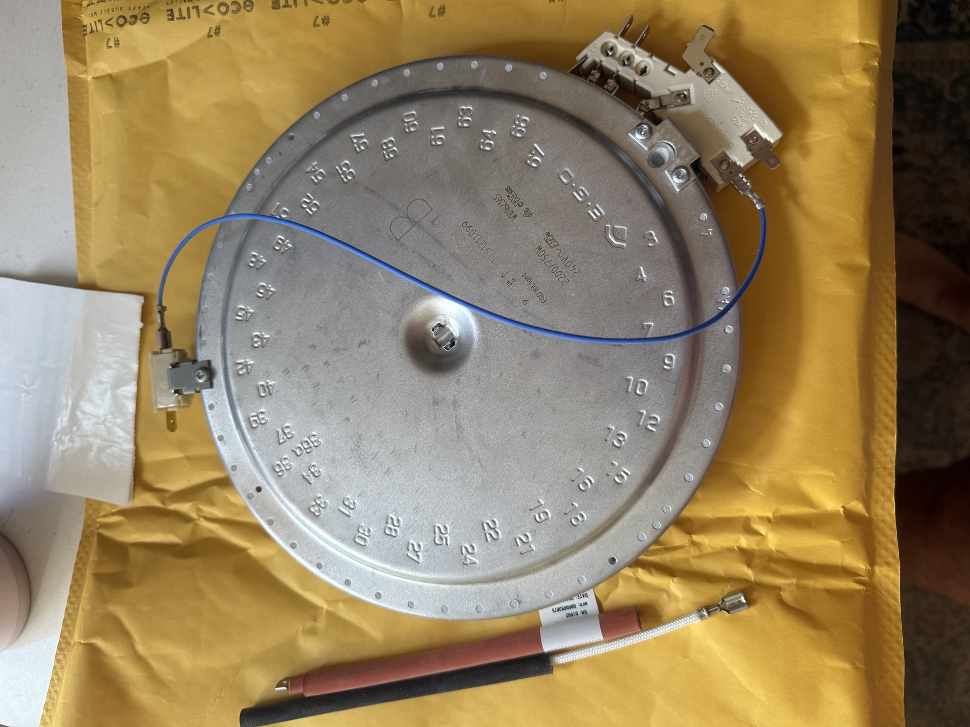
Important: W10823709 is the OEM replacement dual radiant element and replaces older numbers including 74004556. The replacement has a different terminal layout, so do not reconnect wires simply by matching their physical location on the old element.
Tools
Phillips screwdriver
1/4" nut driver/socket as needed
Needle-nose pliers
Masking tape or wire labels
Phone/camera for photos
Work gloves
Step-by-step
1. Disconnect power
Turn OFF the range’s double-pole circuit breaker.
If accessible, unplug the range as well.
Verify the cooktop and oven controls are completely dead before continuing.
This is a 240-volt appliance. Do not work on the element with power connected. Whirlpool’s replacement guidance also specifies disconnecting power before installation.
2. Open the cooktop
Open the oven door.
Locate the two screws underneath the front edge of the glass cooktop.
Remove those screws.
Carefully lift the front of the glass cooktop upward.
Support the cooktop securely so it cannot fall.
This two-screw/lift-up arrangement is documented on this Maytag range family.
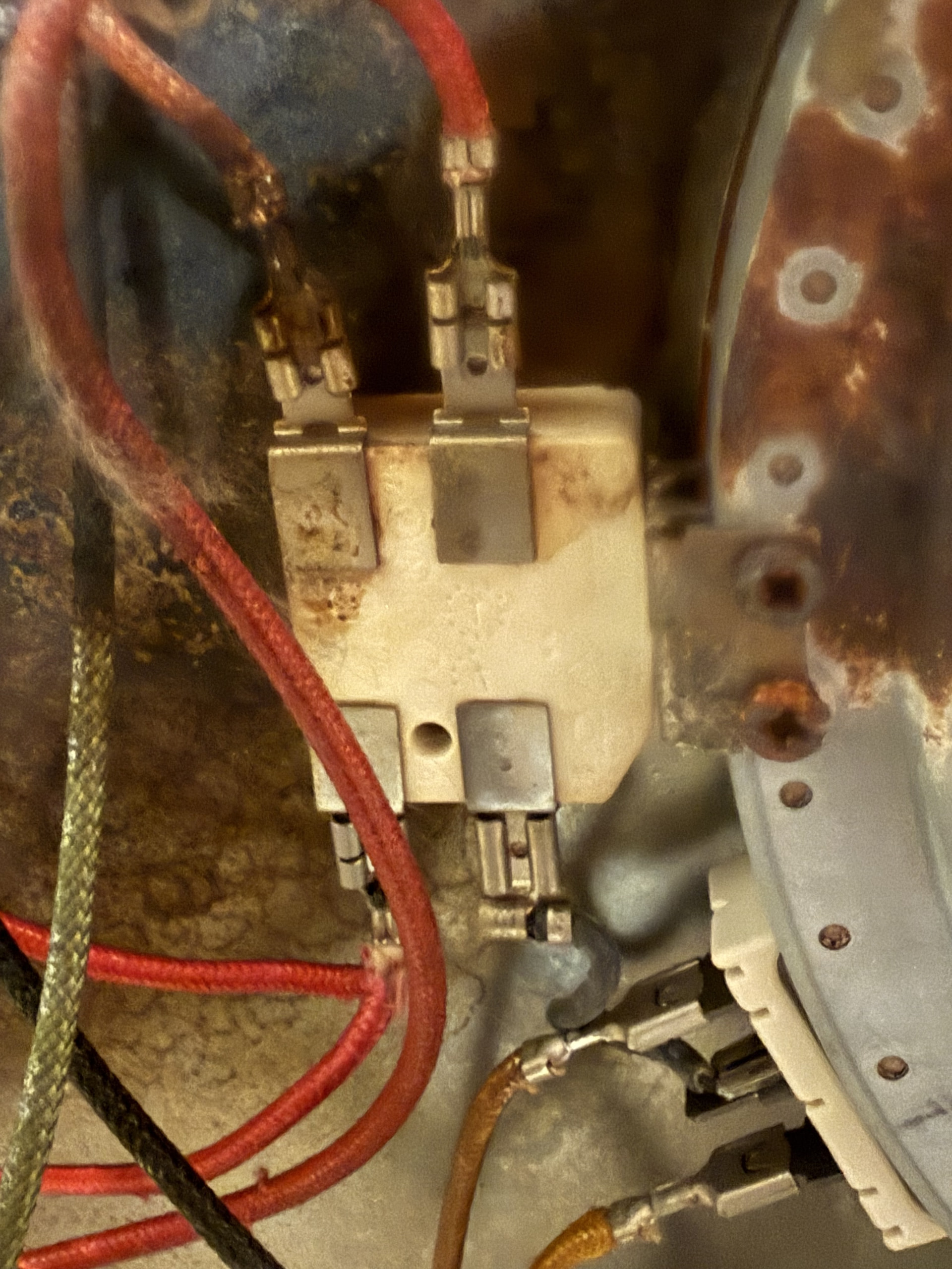
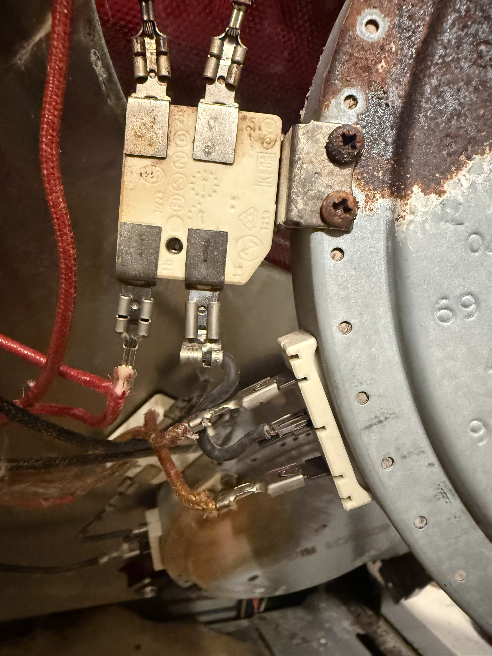
3. Photograph the OLD burner before disconnecting anything
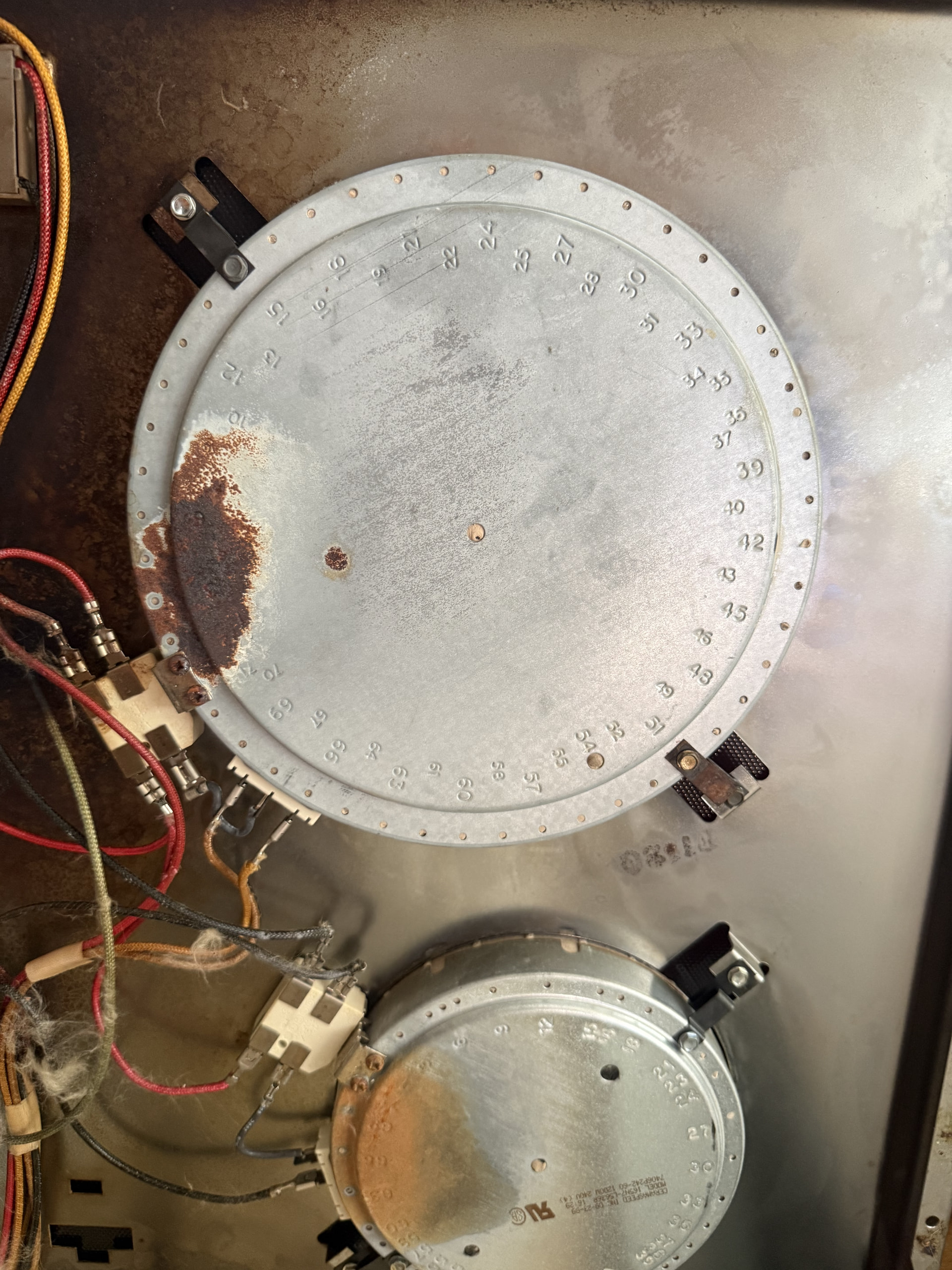
Take one clear overall photo.
Take close-ups showing every wire and terminal.
Make sure the terminal markings/numbers on the old limiter are visible.
Label each range wire according to the old terminal designation, not merely “top,” “bottom,” “left,” or “right.”
This is especially important because owners installing W10823709 report that the replacement’s connections are located differently from the original.
4. Note the mounting-bracket positions
Before removing the old element, note which numbered/lettered mounting holes the brackets use.
Mark those locations.
Install the brackets on the new element in the corresponding positions.
This keeps the radiant element centered directly underneath the correct circle on the glass.
5. Remove the old element
Remove the element/bracket retaining screws.
Lower the old element enough to reach its terminals.
Disconnect wires by gripping the metal connector, not by pulling on the wire.
Keep your photos and labels intact.
6. STOP here before transferring wires by position
Do not connect “upper-left old terminal” to “upper-left new terminal.”
The W10823709 limiter/terminal block is redesigned. Reports for this replacement specifically note that the terminals moved, and the internal connections can run in a different direction. One older external jumper may also be eliminated because the new element incorporates that connection internally.
7. Match the electrical functions
Compare the terminal markings on the OLD element with the markings on the W10823709.
Trace which terminals feed the inner heating coil.
Trace which terminals feed the outer heating coil.
Identify the limiter/hot-surface-indicator connections.
Transfer each range wire according to its electrical function/terminal designation, not its physical position.
Do not guess at this step. Some installations require a different wire arrangement, and some older configurations contain a jumper that is not used the same way on W10823709.
8. Install the new element
Position W10823709 under the glass.
Align the mounting brackets with the locations you marked earlier.
Install and tighten the bracket screws.
Confirm the element is centered beneath the burner outline.
Confirm no wire is touching the radiant heating surface.
9. Check every connection
All push-on terminals should fit firmly.
No connector should be partially installed.
No bare conductor should be exposed.
Make sure wires aren’t pinched between the cooktop and range chassis.
Recheck your wiring photos before closing the cooktop.
10. Lower the glass cooktop
Remove the support.
Carefully lower the cooktop into place.
Reinstall the two front retaining screws.
Do not overtighten against the glass assembly.
11. Restore power and test
Restore the breaker.
Test the burner on LOW first.
Verify the inner element cycles normally.
Select the dual/large setting.
Verify the outer ring comes on.
Verify the surface-hot indicator operates normally.
Turn the burner OFF and confirm it shuts down.
Before you do Step 7
Because your old element and W10823709 have different connections, send me:
A clear photo of the old element showing all connected wires and terminal markings, and
A clear photo of the W10823709 terminal block/limiter.
I can then map the old connections to the new element individually rather than having you guess at the changed terminal arrangement.