My Maytag range MGR4452BDW has a control panel on which the “more” button does not work. I ordered the replacement part but it is not what was pictured and the wiring is completely different. The panel is p/n AP4397197.
The old (broken) panel only has power and the thermocouple running to it. Can anyone tell me where to connect these on the “new” panel?
Did you purchase it from APP?
What is the part number written on the box in which you received the part?
Can you post a picture of the old part?
Here are the breakdown diagrams and Replacement parts for MAYTAG MGR4452BDW RANGE- S/C F/S GAS | AppliancePartsPros.com
Gene.
Gene,
Yes - I purchased the part from APP.
The part number I ORDERED is AP4397197. The part number on the box is 5701M748-60. My guess is that is the Whirlpool part number.
The photograph on APP’s site for the AP part number “looks” like the original I want to replace. The part I received is black - which I guess I can live with - but there are no labels or schematics that show where the power & thermocouple need to be connected. If you could e-mail me the schematic for the new part I’d be all set. I could make an educated guess but I don’t really want to smoke a $ 170 part.
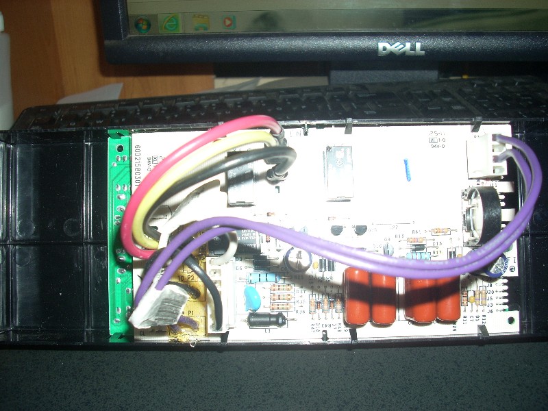
I believe I was successful in attaching a photo of the current part. You will see the power connection (lower right, red terminal block) and the thermocouple connection (white wires, white terminal block).
The new board looks nothing like the old board. The new one has some spade connections, some pin connections and 2 terminal boards.
I just need to know where to connect power & thermocouples.
Thanks for your help.
DSCN1972.JPG (115.3 KB)
I do not see any difference in electrical connections between these two parts. The picture from the APP site is bellow:
You can see the power connections on the right side and the oven sensor connections on the left of it.
If the new part looks different, please post a picture of it.
Gene.
Gene,
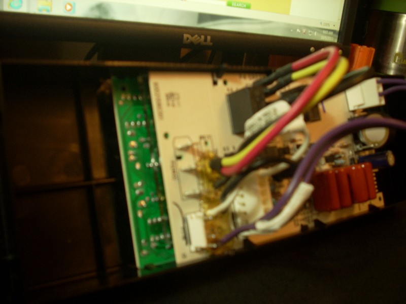
If what you posted is what I had received we wouldn’t be having this conversation. The new board looks nothing like what is pictured on your website! Like I said - the pix on the site shows a WHITE face with the board you posted. What I received is this. The next pix is of the lefthand side of the board. There are three spade lugs coming up from the board and three pin connectors as well. The final pix is of the right side of the board where you can see two purple wires rising from a terminal block.
IF you can get your hands on one you’d see my dilemma. I’m a EE - so I’m no dummy. Can I get a schematic? I don’t need board-level stuff - simply the power and thermocouple connections.
DSCN1975.JPG (132.6 KB)
DSCN1990.JPG (73.3 KB)
DSCN1991.JPG (76.7 KB)
I forwarded this information to the APP research department. Someone will contact you shortly.
Gene.
Don’t bother Gene. I got it.
Had I simply removed the connectors from the original board I would have easily found the correct connections. DUH!
It is up & running.
Thank you for your help!
You are welcome. I’m glad you were able to fix it.
Gene.