Jenn-Air JES9750 Electric grill/range - Touchpad control replacement part# [FONT=‘Arial’,‘sans-serif’]AP4094903[/FONT] Two of the touchpad buttons stopped working so I wasn’t able to turn the oven or broiler on/off. As all else was fine, and the range is only about 5 yrs old, I was pretty sure the touchpad had failed. It’s a DIY project, but be prepared for some tough disassembly and reassembly. The touchpad is part of the entire front panel that contains the heater control knobs and the little red on-buttons. The entire unit is made of cast iron and comes only with the touchpad, so you must take everything off the old panel and reattach it to the new one. The unit sells for $200-$300 online. I bought my unit from AppliancePartsPros.com. Their price was the lowest and their service was terrific. A local repair shop quoted me $500 to do what cost me about $210 (and a little sweat.) Here’s what I did to complete the repair. I hope this will be helpful to any of you planning to do the same. Disassemble and remove the old panel – · Unplug the range or cut the circuit breakers before you proceed! · Remove the 4 disks from the control knob posts. · Unscrew 4 screws; 2 on the left side of the panel & 2 on the right side. · Open the oven door part way and pull it up to remove and make it easy to unscrew 4 screws on bottom side of the panel. · Next, gently pry the panel up from the bottom while pulling it towards you to disengage. There’s a small hidden rail at the top of the panel. The panel will now come loose. · [FONT=Calibri][COLOR=#000000]You will now need to support the panel on a high table or lap, as it will be attached to the stove by a million cables – all of which must be removed before you can complete the job.
[/COLOR][/FONT] · Unscrew 2 screws holding each knob in place. These have a small rubber washer that probably will have deteriorated over time. You can find replacements at the hardware store. · Behind the control panel are small white light boxes (about 1”x1/2”x1/2”) attached to the red plastic on-buttons for each of the 4 knobs. Gently slide each white box sideways to separate the box from the red light posts behind the control panel. · Now, the only thing keeping you from removing the panel are the million wires plugged into the circuit board behind the panel’s touch pad. · Before you remove the wires, take several color photos of the ‘rats nest’ and print them. Make sure you can see where every wire goes. Once you’ve mapped this out, you’re ready for the final disassembly.
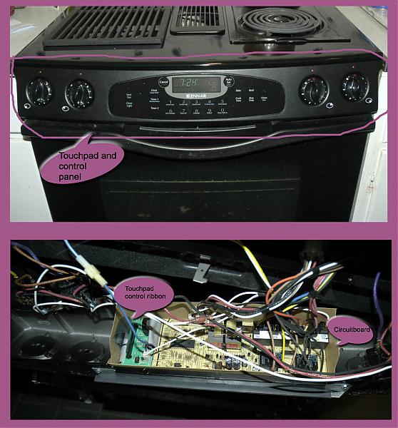
· Pull the wires and wire harnesses off the circuit board. o Wiggle the wire harnesses (about 4 of these) gently and pry them off. o The touchpad wire ribbon is a thin plastic film with about 12 metal leads embedded in it. Observe which direction the ribbon is attached before removing it. To remove it, bend the clip (like a small bar) on the black plastic socket away from the ribbon. This will unplug 2 small pins that hold the ribbon in place. Pull the ribbon up out of the socket. · Unscrew the screw from each corner of the circuit board. An insulator cardboard liner is held down by the screws. You will need to put this back in place when reassembling the panel. · Remove the rail from the top of the panel and save. · Finally, push the little red plastic on-buttons out of the old panel and save them. · Congratulations. Disassembly complete. Assembly Your mission is to put everything back where it came from. By now, you’re familiar with the connectors and wires, so you’ll know how to reattach them. It will help if you can get someone to hold the unit while you reassemble the wires and circuit board, but it can be done alone. Just put things back in this order: · Reattach the rail to the top of the new panel. · Gently push the new touchpad wire ribbon into the black socket on the circuit board until it is firmly seated and snap the retaining bar with the 2 pins into the ribbon. · Screw the circuit board onto the panel, attaching the insulator liner before screwing the panel in. · Reattach all the wires and wire harnesses to the circuit board. Here’s where your photos are a must. Most of the cables are color coded, so you can’t really screw things up, but there are 2 black wires that look alike. Be sure you push them onto their respective prongs. · Screw each of the control knobs back in place. · Push the little red on-buttons back into the panel. · Slide the white light boxes over the red plastic posts. · Check to see that all wires are firmly attached. · Slide the top of the panel up underneath the top of the range, catching the rail, and then push the bottom of the panel into place. This will take a bit of wiggling and some force to put the panel back into the range. · Put the 4 screws back into the sides of the panel. · Put the 4 screws back into the bottom of the panel. · Put the round control disks back on the knob posts. · Congratulations again. You’re ready to return power to the range and try it out. You should see an initial message in the panel saying, SET TIME, and the clock will be displaying some time. A final note: I found that the screws were attached with extreme torque. You may need to apply a drop of WD-40 and wait a bit so you don’t strip the screw heads. I had to drill out a screw holding the circuit board because of this. Take your time. Be prepared to spend 2 hours completing this job. jes9750_control_panel.jpg (63.7 KB)
Would you use the same instructions to replace the Control Panel on a Jenn Air model JES9900BEF? How would the instructions change? Which part do i need to order?
I’m not an appliance expert. You could call one in to check out the problem (probably $75 charge.) If the problem is with the control panel, check with the AppliancePartsPros for the correct part and give it try. If the range looks like mine (see pictures,) I’d expect your control panel assembly will be quite similar. Be sure to take color digital photos as you disassemble the range. It will help tremendously in reassembling the parts.
Thank you for posting those instructions–I just completed the job and my stove works perfectly. I have to say that I’m not at all mechanical, but the job was pretty easy and you gave me the confidence to do it myself. Total cost was $212 versus the $400 I was being quoted for someone else to do it.
I would add just the following little things to what you wrote:
Be extra careful when “unlocking” the wire ribbon harness. Mine snapped off but, with some paper tape, I got around the fact that part of it broke–in other words, the new piece fits in fine
When you remove the little wire harnesses, a needle nose plier is useful (they are on tight). I marked the forward facing piece of each with an X so that I remembered how they fit back
there are 3 black wires to teh circuit board that you will remove but they all can be interchanged (they are all spliced together)
after you remove the little rail on the top, you will also need to remove another rail on the bottom. Be sure to take a picture of this too–you’ll need that when reattaching this bottom rail.
And there are not a million wires…probably only about 10 separate wires and harnesses. I know you were kidding but you made it sound way worse than it was!
Only other comment is that I wish JennAir was smarter about that stupid touch pad and its buttons. When you get the package in the mail, you will shake your head like I did about the way they designed it (with the buttons “embedded” in a big hunk of metal).
Thanks for your comments, BigEdinVancouver. I’m delighted that you were able to use the notes and save yourself a bundle. Others will benefit from your notes as well. BTW, Vancouver is one of my favorite cities.
Hi Guys
Thanks rzidle for giving me the confident and courage to take this repair project on myself. Hat tip to BigEd too.
So I ordered my part online and got a great price $185 plus $10 shipping. Printed out the step by step instructions and followed the script up until it came time to pull the wires. My wife was home so I was grandstanding on how I was going to accomplish this part swap out and gave her an overview. So she comes up with “Why don’t you just unscrew the 4 screws and lift the circuit board out?”
So that’s what I did. The board came out and I swapped out the bracket and 4 red lights on the control panel and screwed the circuit board back in. This whole thing turned out being ridiculously easy.
Thanks again all. I couldn’t have done it without you.
After living with this gradually deteriorating touchpad issue for years and years (we don’t cook much!), we finally got to the point of having to do something about it when the vent wouldn’t turn on anymore. We were to the point of considering replacing the range with an unvented model, because we would rather be boiled in hot oil than give JennAir any more of our hard-earned money. We obtained the part from AppliancePartsPros.com (somewhere around $250 these days) and printed your instructions. We tackled the repair yesterday, and within 45 minutes, everything was working perfectly again! It’s a miracle, we can set our clock at a time other than 2:22 (the two was the only working touchpad button remaining)! Like nuhigher, we did not find it necessary to remove the “million wires” from the circuit board. We simply unscrewed the four screws to release it, and replaced the ribbon. The photos we took turned out to be unnecessary, as well, since we didn’t have to replace the million wires. But rzidle, we are forever in your debt! Thank you!!!
So glad your project was successful. I learned about leaving the wires intact from another brave person. Let’s hope others with faulty touch pads will be encouraged to DIY. Thanks for your note. Bob
These instructions were right on the money. Much easier than expected. The wiring was simpler in my touchpad and only 2 wires needed to be marked for reassembly. The only tricky part of the whole procedure was keeping track of the 18 or so little screws, pulling the pad out (requires some force and maneuvering) and putting the pad back in (clock was surrounded with a heavy cardboard boxy thing that kept getting hung up). Since I thought it would be more difficult than it was, I hired a Jenn-Air authorized service tech to put it in ($140). I ended up having to help him and read these instructions to him. It’s definitely and easier job with an assistant. Also, I saved quite a bit on the touchpad by ordering on line from Easy Appliance dot com (I paid about $180 incl shipping as opposed stores and websites selling at $285).
I have a problem with my broiler will not turn off jenn-air jes-9760. By searching I think there is a circuit board that drives the touch pads is that circuit located on the control assembly? Wished I had the wiring schematics.
THANK YOU, THANK YOU, THANK YOU, I subscribe to Choice Warranty and they would not cover the repair/replacement of the control panel. They sent me a check for $450. So I ordered the part and fixed it myself thanks to you. If I had known it was this easy, I would have done it in 2006 when it first started to fail. Over time, I got the fatal F-7 error, so I had to do something about it.
Saw a youtube video about lightly cleaning corroded ribbon cable ends with a pencil eraser instead of replacing. Thanks for the disassembly instructions.
Saw a youtube video about lightly cleaning corroded ribbon cable ends with a pencil eraser instead of replacing. Thanks for the disassembly instructions.
Just finished my Jenn-Air Control Panel Installation. I could not find a Video on it, but your written instructions were just as good. I especially needed your instruction on the Ribbon Installation! Thanks!
Additional comments for those doing this in the future:
I’d recommend removing the four Phillips head screws that hold that bottom bracket to the oven. Having that bracket remounted onto the panel (but not onto the oven) before panel placement made things much easier. I might have had to have the panel partially in place and then slid the bracket onto/into the panel, because the door lock was sorta in the way, but I don’t recall, and I sure as heck didn’t feel like taking it back apart to check, lol.
The tip about the little white light boxes (on the red plastic light transmitters) was especially helpful. I’d have broken them. Mine slid off to the right and slide back on to the left, btw. Push the little red pieces out from the back.
The ribbon clip on the circuit board: the moving part slides toward the center of the panel (so, to the right). Put your thumbnails on the ends and your index fingers on the little bumps that point toward the center of the panel and pinch, and the bracket your thumbnail is holding will slide toward the center.