[SIZE=2]Hello all,
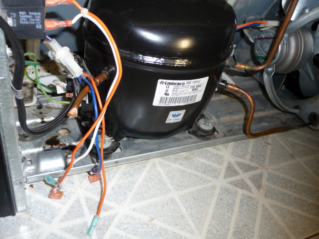
After tech removed the original starter relay he did not put the old one back ( long story I was’nt around but it was a bad one ). I now have the new version replacement and am at stand still as to the wiring hook up. I have seen the schematic but still unsure as to how to read it. I believe I also have a run capacitor on this unit which leaves me with 4 wires to connect to the starter relay with only 3 spades. I’m sure one of these wires must be ommitted and the others attached. From the harness the blue and orange wire also continue to the condenser fan. Then orange and white from the run capacitor.
Can anyone help???
I took some pics to help.
Thanks,
gottado
[/SIZE]
P1000875.JPG (136.9 KB)
P1000876.jpg (41.8 KB)
Looking at the relay
[COLOR=Blue]Blue wire [COLOR=Black]to the Common terminal (on top)
Double [COLOR=DarkOrange]Orange wire[COLOR=Black] goes to [/COLOR][/COLOR][COLOR=DarkOrange][COLOR=Black]Run (right side) the other half goes to terminal on capacitor.[/COLOR][/COLOR][/COLOR][/COLOR][COLOR=Blue][COLOR=Black][COLOR=DarkOrange][COLOR=Black][COLOR=Blue][COLOR=Black][COLOR=DarkOrange][COLOR=Black]That is why only three pins on PTC[/COLOR][/COLOR][/COLOR][/COLOR][/COLOR][/COLOR][/COLOR][/COLOR]
[COLOR=Blue][COLOR=Black][COLOR=DarkOrange][COLOR=Black]White/Wire from Start (left side) goes to other capacitor terminal.
[COLOR=Blue]Blue[COLOR=Black]/[COLOR=DarkOrange]Orange[COLOR=Black] to fan motor. Also to power supply.
[/COLOR][/COLOR][/COLOR][/COLOR]
[/COLOR][/COLOR][/COLOR][/COLOR]
Please click one of the Quick Reply icons in the posts above to activate Quick Reply.
[QUOTE=icehouse;41085]Looking at the relay
[COLOR=Blue]Blue wire [COLOR=Black]to the Common terminal (on top)
Double [COLOR=DarkOrange]Orange wire[COLOR=Black] goes to [/COLOR][/COLOR][COLOR=DarkOrange][COLOR=Black]Run (right side) the other half goes to terminal on capacitor.[/COLOR][/COLOR][/COLOR][/COLOR][COLOR=Blue][COLOR=Black][COLOR=DarkOrange][COLOR=Black][COLOR=Blue][COLOR=Black][COLOR=DarkOrange][COLOR=Black]That is why only three pins on PTC[/COLOR][/COLOR][/COLOR][/COLOR][/COLOR][/COLOR][/COLOR][/COLOR]
[COLOR=Blue][COLOR=Black][COLOR=DarkOrange][COLOR=Black]White/Wire from Start (left side) goes to other capacitor terminal.
[COLOR=Blue]Blue[COLOR=Black]/[COLOR=DarkOrange]Orange[COLOR=Black] to fan motor. Also to power supply.
[/COLOR][/COLOR][/COLOR][/COLOR]
[/COLOR][/COLOR][/COLOR][/COLOR][/QUOTE]
What do you think about using one of those 3-N-1 “hard start” kits on an older unit?
Still not sure as to hook up per Icehouse’s post…sorry
Again there are four wires each with a female disconnect:
One Blue and one Orange from Harness coming down from ADC pairing off to the relay and continuing to condenser fan.
Also one White and one Orange coming from Run Capacitor
The new Overload/Relay has only 3 terminals. Do I double up the orange wires at relay???
Instruction sheet for new relay kit is attached.
12002783
Thanks
Overload----Relay12002783.jpg (71.9 KB)
Used 3in1 many times. Keep one with a power cord to quick check compressors.
I’ve read they are not recomended
[quote=gottado;41511]Still not sure as to hook up per Icehouse’s post…sorry
Again there are four wires each with a female disconnect:
One Blue and one Orange from Harness coming down from ADC pairing off to the relay and continuing to condenser fan.
Also one White and one Orange coming from Run Capacitor
The new Overload/Relay has only 3 terminals. Do I double up the orange wires at relay???
Instruction sheet for new relay kit is attached.
12002783
Thanks[/quote] Nothing showed up. However the blue lead from ADC connects to the top (C) terminal and blue lead from condenser fan.
The orange lead from the ADC connects to the terminal on the left (R) and the orange lead from the capacitor doubles up on this terminal, as well as the orange lead from the condenser fan.
The white lead from the capacitor attaches to the terminal on the left (S) 
Bozos have the pin configuration “upside down” So now [COLOR=Blue]blue [COLOR=Black]is on bottom (C), [COLOR=DarkOrange]orange [COLOR=Black]is on right (R) White is on left (S).
All [COLOR=Blue]blue wires [COLOR=Black]together, and all [COLOR=DarkOrange]orange wires [COLOR=Black]together. :)[/COLOR][/COLOR][/COLOR][/COLOR]
[/COLOR][/COLOR][/COLOR][/COLOR]
[QUOTE=icehouse;41512]Used 3in1 many times. Keep one with a power cord to quick check compressors.[/QUOTE]
We must have been trained by the same person. I have one on a test cord, too.
[QUOTE=gottado;41516]I’ve read they are not recomended[/QUOTE]
They’re not recommended for units that are still covered by warranty. Some techs believe they are a waste of money, saying that a compressor that needs one is already on its deathbed. I believe if using a 3-N-1 can buy a customer another year of service, it is worth the cost.
I just run a power cord and hook it up directly to the compressor, bypassing the start package  Just playin!!!
I love the 3 in 1 with a power cord, very quick to diagnose a dead compressor. You know if you have a compressor that wont start, I have had some luck (not alot) by hooking up 2 to 3 3 in 1’s in series to try to get the compressor running.
I’m a big believer in using test cords. I use them to test water valves, motors, pumps and compressors. They’re great for quick diagnoses.
I also have the “Annie Hermetic Analyzer”, but use the 3in1 with power cord when time does not allow.
Never heard of an Annie Hermetic Analyzer. I just ohm out the windings.