Rank: Member
Groups: Registered
Joined: 11/9/2012(UTC)
Posts: 3
|
I hope you're still here Joe, I've got a question. I too replaced the switch per your instructions and tested. The dual element burner turns on both large and small rings but only on high. When I turn the dial I can hear the thermostat click but no reaction from the burners? Was my switch not the problem afterall? I replaced the infinate switch because the RF dual burner only went on to high with no adjustment to low? Help
|
|
|
|
|
|
Rank: Advanced Member
Groups: Moderators
Joined: 7/14/2010(UTC)
Posts: 5,222
Was thanked: 1 time(s) in 1 post(s)
|
Zinger, So far everything sounds normal, and operational. You did need a new infinite switch. If the burner remains on "HI" Regardless of setting, this indicates the "cycling" switch and circuit contacts have arced together and the switch needs to be replaced. When you use the dual element burner, the "low" setting(right side of switch) operates the inner ring only. When you select the "HI" (left side of the switch) this operates both the inner and outer elements, and they cycle off and on in unison. Right now, you'll need to check and make sure the Red L2 wire is attached to the P2 terminal of the new switch. (The L2 red will be "hot" 120 VAC as long as there is power applied to the range, and common to all the infinite switches). The other two red wires will attach to the number two(2) terminal of the switch (these red wires will enter the wiring harness junction connector and attach to the heater elements in the cooktop). If the wiring at the new switch is not correct, you wont have any L2 power to the element and it wont work. Thanks
|
|
|
|
|
|
Rank: Member
Groups: Registered
Joined: 11/9/2012(UTC)
Posts: 3
|
Hi Joe, thanks for the quick response. I wired the new switch exactly like the original poster was advised. Here is the wiring from old switch to new: #1 Blk to S2 #2 Dual Blk wires to P1 #3 Tan (Brn) to 4 #4 Red to 2 #5 Dual Red wires to P2 #6 Yellow to 4a There was no markings on old switch to determine the "L2" labeling, just numbers? I was thinking maybe I need to remove the glass top and see if any of the wires to the element are bad or loose before possible ordering a new element? Jes9800AAB -oven old switch - 7403P406-60 new switch - 12002125 sure would be great if they would just continue to make parts the same so replacing would be easier! I didn't split the dual red wires that went to the #5/N terminal on the old switch as the diagram that came with the new switch was hard to determine what connection I had. The instructions given to original poster was for my same unit so I did what was advised. 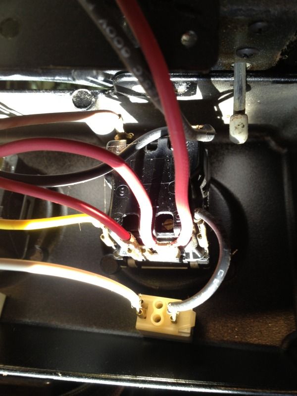
|
|
|
|
|
|
Rank: Advanced Member
Groups: Moderators
Joined: 7/14/2010(UTC)
Posts: 5,222
Was thanked: 1 time(s) in 1 post(s)
|
Zinger, Everything sounds and looks correct. Here's another check to make, using a multimeter, set for 240 VAC ( You need to be careful, this is a live voltge test) re apply power to the range, at the new infinite switch check across P1 (dbl black wires) and P2 (double red wires) switch terminals, you should have 220 to 240 VAC wether the switch is off or on. This will confirm you have the proper power supply and the switch is wired correctly. You can then turn the switch on low and check for 220 VAC across red and tan at the element, then high setting red to yellow. If you have the correct voltage, then replace the element, if not, you'll need to trace wires back to the switch.
|
|
|
|
|
|
Rank: Member
Groups: Registered
Joined: 3/9/2013(UTC)
Posts: 1
|
Joe M - YOU ARE THE MAN! I have a JES9800AAB Jenn Air and the wiring instructions on page 1 of this thread were spot on.
I thought I'd post some additional comments that hopefully will help someone else with the same model range/oven.
To get to the switches, there is no need to take the glass top off. I slid my unit out just enough to expose the 2 black screws on each side of the control panel. I removed those 2 on each side, then opened the oven door and removed the 4 black screws holding the control panel to the oven. Be sure to have someone ready to "catch" the control panel because it will be ready to tip out at this point. I only removed the knob and knob screws for the one switch I was replacing (in my case, the far right one). Having a helper hold the control panel tilted out, I was able to disconnect the defective switch and reconnect the new switch. My replacement (12002125) came with 2 jumpers. I ended up using the jumper that had the right angle connector on it and was thinner wire than the other jumper provided. The other jumper didn't seem to fit. I plugged the uninsulated right angle end into P1 with the wire facing outside the switch and the insulated end into S1.
Hope this helps someone else.
Thanks AppliancePartsPros for the great price on the replacement switch and the priceless advice for installing it!
|
|
|
|
|
|
Rank: Advanced Member
Groups: Moderators
Joined: 7/14/2010(UTC)
Posts: 5,222
Was thanked: 1 time(s) in 1 post(s)
|
Originally Posted by: jhcrowman  Joe M - YOU ARE THE MAN! I have a JES9800AAB Jenn Air and the wiring instructions on page 1 of this thread were spot on.
I thought I'd post some additional comments that hopefully will help someone else with the same model range/oven.
To get to the switches, there is no need to take the glass top off. I slid my unit out just enough to expose the 2 black screws on each side of the control panel. I removed those 2 on each side, then opened the oven door and removed the 4 black screws holding the control panel to the oven. Be sure to have someone ready to "catch" the control panel because it will be ready to tip out at this point. I only removed the knob and knob screws for the one switch I was replacing (in my case, the far right one). Having a helper hold the control panel tilted out, I was able to disconnect the defective switch and reconnect the new switch. My replacement (12002125) came with 2 jumpers. I ended up using the jumper that had the right angle connector on it and was thinner wire than the other jumper provided. The other jumper didn't seem to fit. I plugged the uninsulated right angle end into P1 with the wire facing outside the switch and the insulated end into S1.
Hope this helps someone else.
Thanks AppliancePartsPros for the great price on the replacement switch and the priceless advice for installing it! Jhcrowman, Thanks We appreciate your comments, We're glad we were able to help you out. Thanks for the update of your experience, it will come in handy for other DIY's reviewing the Repair Forum and taking on a similar repair. Great Job !!! Thanks Again,
|
|
|
|
|
|
Rank: Member
Groups: Registered
Joined: 8/2/2013(UTC)
Posts: 3
|
I need help! I have wired the Dual infinite switch to the wiring instruction but when I leave the two red wires together on P2 the dual burner does not work. When I put the red wire coming from power to the P2 and the red wire going to the next switch in line on 2 the dual burner works but rest of burners do not. It is on a Jennair cook top. Model number CVE3400W.
|
|
|
|
|
|
Rank: Advanced Member
Groups: Moderators
Joined: 7/14/2010(UTC)
Posts: 5,222
Was thanked: 1 time(s) in 1 post(s)
|
Originally Posted by: mdeudy6565 I need help! I have wired the Dual infinite switch to the wiring instruction but when I leave the two red wires together on P2 the dual burner does not work. When I put the red wire coming from power to the P2 and the red wire going to the next switch in line on 2 the dual burner works but rest of burners do not. It is on a Jennair cook top. Model number CVE3400W. Mdeudy, Presumaly we're working with the Part number: AP4008679

Dual Infinite Switch Kit. You almost had it. The Red wire, common to all the infinite switches will attach to the P2 terminal of the new switch. The remaining Red wire ( common lead to the left rear element) will attach to the #2 terminal of the new switch. As long as the remainder of the wiring to the switch is proper, you should be fine.
|
|
|
|
|
|
Rank: Member
Groups: Registered
Joined: 8/2/2013(UTC)
Posts: 3
|
I switched the wires and it trips the breaker. The switch for the dual burner is first inline from the power. One of the red wires goes to the power and the other red wire goes to the next switch and so on to the other two then to the dual burner.
|
|
|
|
|
|
Rank: Advanced Member
Groups: Moderators
Joined: 7/14/2010(UTC)
Posts: 5,222
Was thanked: 1 time(s) in 1 post(s)
|
Originally Posted by: mdeudy6565 I switched the wires and it trips the breaker. The switch for the dual burner is first inline from the power. One of the red wires goes to the power and the other red wire goes to the next switch and so on to the other two then to the dual burner. Hopefully the new switch was not damaged, but we'll see in a minute. You'll be working with both, the left rear "dual" infinite switch and the right front infinite switch. At the left rear dual switch the double red wire attached to the N terminal on the original switch, will be attached to the P2 terminal of the new switch. At the right front infinite switch the double red wires attached to the L2 terminal, will need to be separated. The red wire common to all the infinite switches will attach to the L2 terminal of the right front infinite switch. The remaining red wire, which can and should be traced to the left rear element, will need to be re terminated (install terminal on end of wire), and attached to terminal 2 of the new dual infinite switch. When you're done wiring the new dual infinite switch : P1 terminal will have two black wires one end of the jumper wire and black L1 wire common to all the switches (one wire on each P1 terminal). Terminal 4 will have the blue wire to the inner element ring attached to it. Terminal 4a will have the purple wire to the outer element ring attached to it. Terminal S2 will have the orange wire to the indicator light attached to it. Terminal S1 will have the other end of the jumper wire from P1 terminal attached to it. P2 terminal will have the double red wire, from the terminal block and common to all the switches attached to it. Terminal 2 will have a single red wire from the left rear element sensor attached to it. Once you're checked and ensured the wiring is correct, restore power to the cooktop and check the burner for proper operation.
|
|
|
|
|
|
Forum Jump
You can post new topics in this forum.
You can reply to topics in this forum.
You can delete your posts in this forum.
You can edit your posts in this forum.
You cannot create polls in this forum.
You can vote in polls in this forum.
Important Information:
The AppliancePartsPros.com uses cookies. By continuing to browse this site, you are agreeing to our use of cookies.
More Details
Close