My GE WPRE6100G2WT clothes washer won't agitate or spin

Please make sure to click on General above and select the correct appliance type first.

Brand: GE
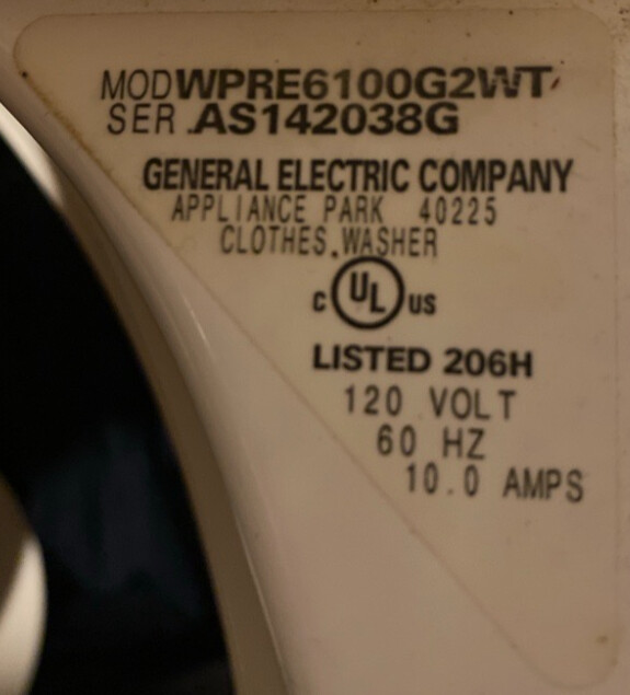
Model Number: WPRE6100G2WT
Main Symptom: doesn’t agitate or spin
What happens & when: all the time, the motor never engages as of earlier this week
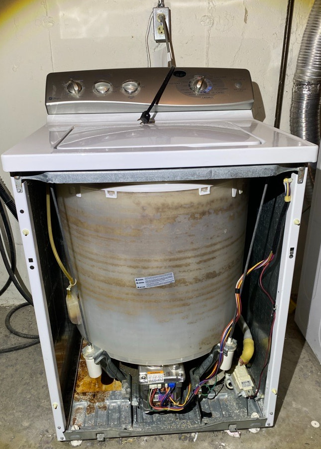
Error Code (if any): Initially I found the green light on the motor flashing once followed by a pause. I reset it and then if flashed normally 1-sec on, 1-sec off. Then I tried to run a spin cycle (it didn’t spin) and when I checked the light again the error code was 4 flashes then a pause. I have since reset it again back to normal, but of course that isn’t “fixing” the problem.

Parts or tests already tried: I found this video from your site (https://youtu.be/Y6yjWT_ec0w) but unfortunately, the very first test step left me scratching my head. The instructor told me to test the voltage on J7, but my controller board has no J7 on it. My guess is that the right 3 red/yellow/blue wires shown in the photo below are the desired wires, but that’s just a guess. I did trace the other end of this set of wires down below connecting to the motor.

I can’t jam the probes from my multimeter down inside the connector like I see on the video, but the end of the connector (around the back of the blue connector as shown in the above photo) has exposed metal so I touched my probes there.
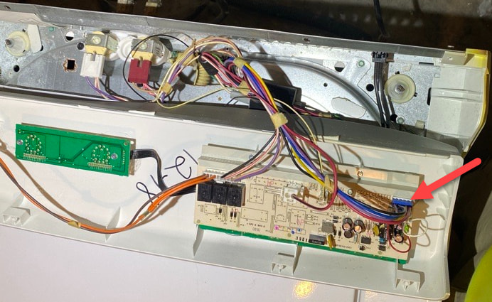
What seems to be happening when I connect my black probe to the red wire and my red probe to the blue wire is that for a few seconds (maybe 10) after starting the spin cycle, my meter reads somewhere in the neighborhood of 12.5 volts but it can fluctuate between 11.5 and 13.1 (ish). It’s kind of hard to do this since the metal behind the connector is a bit slippery and I’m not always positive I’m making a good connection. Anyway, after maybe 10-20 seconds, I seem to lose voltage and don’t get these readings any more. It doesn’t just drop to zero on my meter, sometimes it’s negative a few millivolts. I think my meter just doesn’t know what to display since it’s not getting any solid voltage coming in. I don’t do this kind of thing often so I don’t really have a good frame of reference regarding how to interpret what I’m experiencing.

That’s all the further I’ve gotten with my testing as I didn’t know whether or not I was even starting out on the right foot here.

Photos / video link:
work off this:
31-9145 GE Profile Washers With Electronic Control Mode Shifter Assembly Models WPRE6100 WPRE8100.pdf (1.8 MB)
31-16515 GE WPRE6100G2WT Washer Mini Manual.pdf (862 KB)

Thank you SO much for these manuals. Between the two of them, I believe I now have some successful test results to report. I hope I did this correctly. Here is what I learned.

FIELD SERVICE MODE TEST:

  • Position 0: “88” plus 3 LED’s
  • Position 1: 6
  • Position 2: no lights at all … which I interpret to mean there are no error codes to worry about
  • Position 3: no lights at all … which I interpret to mean there are no error codes to worry about
  • Position 4: H … tub began filling with hot water
  • Position 5: C … tub began filling with cold water
  • Position 6: AL … absolutely nothing happened, no activity of any type, just quiet
  • Position 7: AH … absolutely nothing happened, no activity of any type, just quiet
  • Position 8: P … pump engaged and drained the water in the tub
  • Position 9: SP … absolutely nothing happened, no activity of any type, just quiet
  • Position 10: 3F … absolutely nothing happened, no activity of any type, just quiet

Next, I tested voltages guided by page 39 of the Technical Service Guide (https://forum.appliancepartspros.com/uploads/short-url/sHgpik25jeg27wN4zDMAyUIMmj3.pdf). I repeated each test multiple times to make sure I got consistent results:

  • C2 pin 5 to pin 3 = 118 VAC
  • C2 pin 6 to pin 3 = 118 VAC with lid switch closed
  • C7 pin 1 to pin 2 = 298 VDC during first 15 seconds when in position 6 (AL) of field service mode test
  • C7 pin 1 to pin 2 = 298 VDC after first 15 seconds when in position 6 (AL) of field service mode test
  • C4 pin 5 to pin 1 = 8.9 VDC when in field service mode position 9 (S)
  • C4 pin 5 to pin 2 = 8.9 VDC when in field service mode position 9 (S)
  • C4 pin 5 to pin 3 = 8.9 VDC when in field service mode position 9 (S)
  • C4 pin 5 to pin 4 = 8.9 VDC when in field service mode position 9 (S)

Additionally, I did two other tests:

  1. On page 26 they discuss a fuse which if open will disable agitate, spin and mode shifting. Therefore, I tested continuity of the white/red wire from where it attaches to the motor (C2, pin 3) up to where it connects to the main control board (J11, pin 4). Continuity was present, so I assume the fuse is not blown.

  2. On the bottom of page 39 I read “The mode shift coil connects to C7 connector on inverter/motor assembly. Unplug C7 connector and check continuity. Mode shift coil resistance value is approximately 98 Ohms at room temperature.” I did disconnect C7 but I have no idea how they want me to check continuity. I set my multimeter to KOhms and touched each probe to each pin of the C7 wire connector (i.e. not the pins on the motor) and there was no reading change. I then set my multimeter to test continuity and touched each probe to each pin of the C7 wire connector (i.e. not the pins on the motor) and there was no continuity beep. I then repeated the same tests this time touching the pins on the motor rather than on the wire connector and had the same results. Something tells me I’m not doing what they asked. Maybe somebody can tell me what I’m supposed to do here if I’m not doing it right?

Does the above testing give anybody enough information to tell me what is broken and what I need to replace?

Have you tired this opening and closing lid after powering it down?
MSA PRESENTS THE GE PROFILE WASHER With Mode Shifter.pdf (78.6 KB)

Yes, I have done this a number of times. It successfully reverts the flashing pattern to 1-sec on and 1-sec off, but then as soon as I try to spin again it goes back to the error code flashing 4 times then pausing.

Yes. Those test results narrow this down quite a bit, and I think your mode-shifter test is the key next step.

The 4-flash motor/inverter code points toward a mode-shifter circuit problem, which also fits what you’re seeing: the washer fills and drains normally, but agitate and spin do absolutely nothing.

Your other readings look encouraging. You have 118 VAC where expected, the lid-switch circuit is passing power, and you’re getting about 298 VDC at the inverter/motor assembly. That makes a simple loss of power to the motor much less likely.

For the 98-ohm mode-shifter test, you were very close, but the measurement needs to be made across the two terminals that actually lead to the mode-shifter coil. Unplug the washer first and disconnect the C7 connection. Set the meter to the 200 Ω range if it isn’t autoranging—not kΩ if you have a lower range available. Measure directly across the two mode-shifter coil terminals.

A good coil should read roughly 98 Ω at room temperature. It doesn’t have to be exactly 98; something reasonably close is fine.

If you get OL/infinite resistance/no reading, the mode-shifter coil is open. That would explain the 4-flash code and the failure of both the AL/AH agitation tests and SP spin test. In that case, I would address the mode-shifter/mechanical assembly containing that coil rather than replacing the main control board.

One important point: don’t use the continuity-beep setting as the deciding test here. Some meters will not beep at approximately 98 Ω, even though the coil is perfectly good. We want the actual resistance reading.

Also, the 8.9 VDC readings at C4 during the spin command suggest the control is attempting to communicate with/control the motor. Combined with the motor having its high-voltage DC supply, I’m not leaning toward the main control at this point.

So my next move would be very simple: unplug the washer and get an actual resistance measurement across the mode-shifter coil. If it reads OL/open, you’ve likely found the failure. If it reads around 98 Ω, then we can move on to the motor/inverter and shifter-position feedback tests rather than guessing at parts.

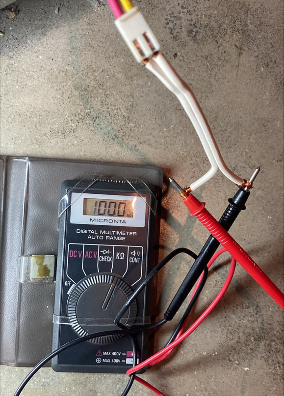
Thank you so much. Here you go. I’m including photos so you can verify that I’m doing this correctly. I unplugged the connector at that motor which runs to the mode-shifter and I tested resistance between the 2 wires that run to the mode-shifter. I had to use a short lead-wire because my probes don’t fit inside the connector. I used 2 different multimeters for comparison.

In this first photo, I used my simpler but newer digital multimeter which I had used in my previous tests. It only has one Ohms setting (K Ohm). When I hook up the probes, the zeros are on solid but the “1” to the left of the three “000” is flashing. I’m not exactly certain what that means.

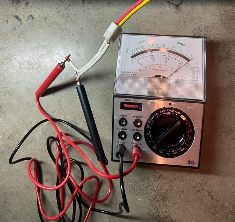
Next, I used my older analog multimeter for the same test. I think I’m supposed to set it at R100 since I want to measure something around 100 Ohms. On this multimeter, when the probes are not connected, the needle is all the way to the left. When the probes are touched together to zero the meter, I adjusted the needle to line up exactly at zero. As shown in the photo below, when the probes are connected to the mode-shifter wires, the needle ends up slightly to the right of zero.

I assume this means there is ZERO resistance and we have a bad mode-shifter?

Yes — you’re testing the correct two wires, but there’s an important issue with how the meter readings are being interpreted.

On the digital meter, the flashing “1” at the far left generally means over-range/open circuit, not 1,000 Ω. So that meter appears to be telling us there is no continuity through the mode-shifter coil.

On the analog meter, R×100 is not the right range for checking a roughly 98 Ω coil. On an analog meter the setting is a multiplier, so R×100 means you multiply the scale reading by 100. That makes it difficult to accurately measure something around 100 Ω. If that meter has an R×1 setting, use that instead.

One more test

Unplug the washer and leave that connector disconnected exactly as you have it.

Set the analog meter to R×1. Touch the probes together and use the OHMS ADJ knob to put the needle exactly at 0 Ω on the far right. Then put the probes across those same two mode-shifter wires.

For a good mode-shifter coil, we’re looking for approximately 98 Ω.

If the analog meter stays toward the left/open side, and your digital meter continues displaying the flashing 1, then the two meters are agreeing: the mode-shifter coil is open.

One other thing caught my attention in your analog-meter photo: the needle appears fairly close to the zero-ohm end of the scale. Because you’re using R×100, that doesn’t necessarily mean the circuit is open. That’s why I don’t want to condemn the shifter based on these pictures alone.

Try R×1 and tell me where the needle lands on the OHMS scale—or send another photo. At that point we should be able to make the call without replacing parts unnecessarily.

Ok, thank you for all that explanation. I redid my tests with just the analog multimeter since there’s nothing to change on the digital one.

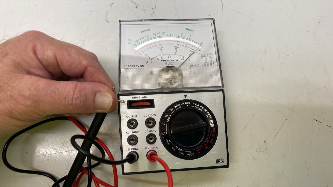
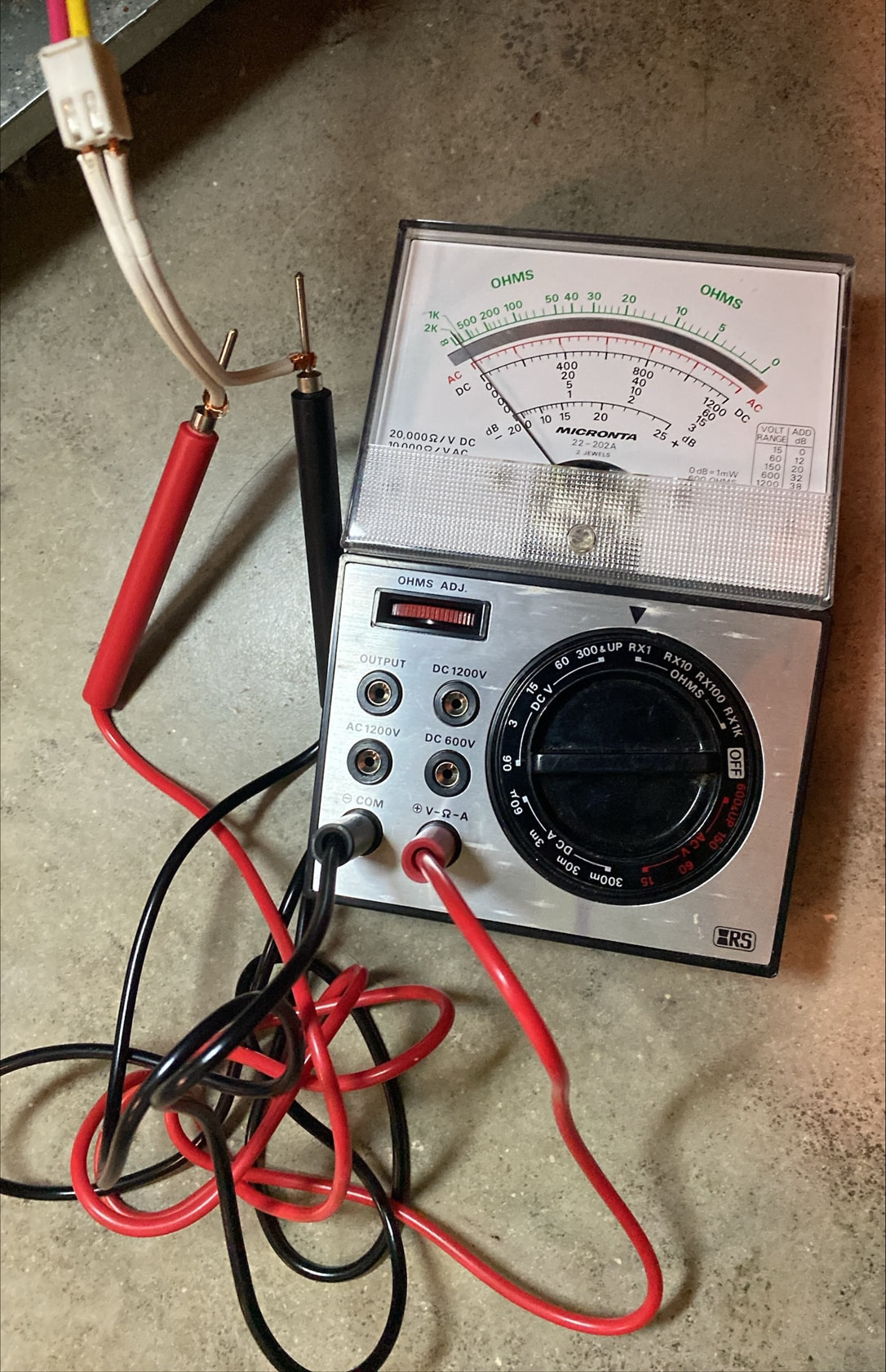
I first calibrated the needle to zero with the dial set to RX1. In the photo it seems to have drifted slightly to the right, but it was on zero when I calibrated it right before snapping the photo.

Then I hooked it up and the needle didn’t budge. It remained right all the way to the left as though I hadn’t connected anything. I even touched the probes together just to make sure I hadn’t goofed something up and the needle jumped right back over to the right and as soon as I would separate the probes with just them connected to the wires, then it would return right back over to the left as if nothing was connected.

Yes — that test result is much more conclusive.

Since you verified the analog meter is working by touching the probes together, but the needle stays all the way to the left when connected to the two mode-shifter wires, the meter is reading infinite resistance/open circuit.

On the GE WPRE6100G2WT, that means the mode-shifter coil is open. A good coil should give you a measurable resistance; it should not behave exactly like the probes are disconnected.

So based on this test:

Meter probes together → needle goes to 0 Ω: meter and leads are good.
Across the two mode-shifter wires → needle stays at ∞: mode-shifter coil is open.
Conclusion → the mode shifter is bad.

You don’t need to worry about the tiny amount the zero adjustment drifted in the photo. That would matter if we were trying to distinguish, say, 90 Ω from 100 Ω. It doesn’t matter here because you’re getting no movement whatsoever.

At this point, I would replace the mode shifter/shaft-and-tube assembly(GE WH38X10017 Washer Mode Shifter & Shaft Assembly | Genuine OEM Part) rather than the control board. This also fits very well with the shifting/agitation problem we’ve been chasing.

Ok, based on our troubleshooting above, I gambled and purchased a mode shifter/shaft-and-tube assembly (GE WH38X10017). It took me a lot longer than I’d anticipated to perform the surgery, but I managed the entire replacement job without too much fanfare. Unfortunately, even with a brand new mode shifter now in my washer, I am back in the same place I was before with ALL the same test results and 4-blink light pattern on the motor. I’ve reset the motor to where it flashes normally, but then as soon as I try to engage any spin or agitate activity, the light switches back to the 4-flash pattern pointing AGAIN to a bad mode shifter.

I measured the resistance on my new mode shifter and it measures 69 Ohms with a brand new digital multimeter I just purchased. I realize that in previous postings above it was indicated that this test should measure 98 Ohms ± 10%, but I asked another technician I know and out of curiosity he tested a couple other brand new OEM mode shifters he had in stock (also WH38X10017) and they all tested at 69 Ohms. So I don’t know if I’m caught in some kind of warp in the time-space continuum, or maybe 69 Ohms is simply the new normal?

Anyway, I’ve done more research on the internet and am being informed that if I’ve replaced the mode shifter with a brand new one and the motor is still complaining that the mode shifter is bad, then something is either wrong with the connection between the motor assembly and the mode shifter or the motor’s controller board has lost it’s mind and the motor assembly needs to be replaced. Unfortunately, I can’t justify spending ANOTHER $350 to repair a 20 y/o washer that probably isn’t even worth that much.

Any other ideas of things for me to try before I give up?

First off, congratulations on tackling that mode shifter replacement! That’s a pretty involved repair, especially on an older GE washer. I can certainly understand your frustration after doing all that work, only to end up with the exact same problem.

The good news is that your latest findings give us a much better idea of where to look. I wouldn’t purchase another motor just yet. There are a couple of checks worth making before calling it quits.

Regarding your GE WPRE6100G2WT, here’s what I’m thinking.

1. The 69-ohm reading may actually be normal

You brought up an excellent point about the resistance measurements. If your new WH38X10017 mode shifter measures 69 ohms, and another technician measured the same resistance on multiple new OEM assemblies, that’s pretty convincing evidence that 69 ohms is normal for those particular parts.

The previously mentioned 98-ohm specification may apply to a different version of GE’s mode shifter. I wouldn’t condemn your new assembly based on that difference alone.

2. Check the wiring between the mode shifter and motor

This would be my next step.

Since the new mode shifter hasn’t changed anything, we need to determine whether the motor control is actually seeing that 69-ohm resistance.

Here’s how I’d check it:

  1. Unplug the washer.
  2. Locate the small wiring connector at the motor that carries the two mode-shifter wires.
  3. Disconnect that connector.
  4. Measure resistance across the two mode-shifter wires at the motor end of the harness.

You should see approximately 69 ohms, matching the reading directly at your new mode shifter.

If you get an open circuit or a much higher reading, inspect the wiring, connector terminals, and any damaged or loose connections.

While watching your meter, gently wiggle the harness. If the reading jumps around or disappears, you’ve probably found your problem.

3. Check for a short to ground

With the washer still unplugged and the mode-shifter circuit disconnected from the motor controller, check each of the two mode-shifter wires against the washer’s metal frame.

You should not have continuity to ground.

If either wire shows continuity, there’s likely a damaged wire or insulation problem.

4. The motor control is becoming a stronger suspect

Here’s what really catches my attention.

You’ve already established that:

  • The original mode shifter appeared to have an open circuit.
  • The replacement measures approximately 69 ohms.
  • The motor resets successfully.
  • The motor immediately returns to the four-flash error when agitation or spin is requested.

If the motor is receiving the correct mode-shifter circuit resistance through the harness, but continues reporting a mode-shifter fault, that certainly raises suspicion about the electronic control built into the motor assembly.

However, a four-flash error doesn’t prove the motor control is defective by itself. We still need to rule out a wiring problem and verify that the controller is operating the shifter correctly.

5. One final electrical test

If the harness checks out, the next step would be checking whether the motor control sends voltage to the mode-shifter coil when agitation or spin is requested.

This is a live-voltage test, so there’s a shock hazard. The circuit must be identified correctly before testing, and the washer must be unplugged when connecting or removing meter leads.

On GE models using this style of mode shifter, the coil is typically operated by line voltage, but I’d want to verify the exact wiring and test points for your model before giving you specific voltage instructions.

If the control isn’t supplying the required voltage when commanded, despite having proper power and wiring, that would strengthen the case against the motor control.

My recommendation

Before spending another $350, I’d concentrate on one simple measurement.

With the washer unplugged, what resistance do you measure at the disconnected mode-shifter connector right at the motor?

If you get the same 69 ohms there that you measured directly at the new shifter, we’ve eliminated a major possibility without spending another dime.

And considering the age of the washer and everything you’ve already invested, I agree that replacing the complete motor assembly might not make financial sense.

You’ve done an impressive amount of troubleshooting, and I’d really like to see you get a definite answer before giving up on this machine.

Jeffrey, before I say anything else, I want to thank you again for all the time you have clearly spent reading what I’ve written and responding in such a thorough and clear way. It has been so helpful and this has been a great learning experience for me… maybe not one I would have otherwise chosen (:wink:), but good anyway I suppose :upside_down_face:.

So working through your last post, in #2 it seems to me that you are asking me to do what I’ve already done. The only way that I know of to measure the resistance of the mode shifter is at the connector where it plugs into the motor. The end where it enters the mode shifter is sealed where it enters the metal housing so there’s no access on that end. So I presume that I’ve already ruled out what you were asking me to rule out. So with the washer unplugged, I unplug the connector shown below from the motor. Then, because the probes on my multimeter don’t fit inside the connector, I made myself a little wire pigtail which I insert into each hole of the connector and then touch my probes to the other end of those wires. That is where I measure the 69 Ohms. It might fluctuate slightly as I wait, but it’s all within a few tenths of an Ohm.

As for #3, with the washer unplugged and the mode shifter disconnected, I tested continuity (listening for a beep) between each of the pins of the mode shifter connector ON the motor and a bunch of metal places around the washer, including the motor housing and even the metal side of the washer. There was no continuity, so it appears there’s no short there at least.

For #5, I’m willing to test this no problem… after all, electricity hasn’t killed me yet :laughing:. Am I waiting for exact line voltage specifications from you before I proceed or am I supposed to look these up somewhere? It will be a bit of a challenge figuring out how to connect my meter while everything is off and in such a way that it remains connected when I plug everything back in. I’ve considered since my original mode shifter is dead, I could just cut off the it’s electrical lead and pilfer the connector for my test, but maybe I’ll come up with a different way as well.
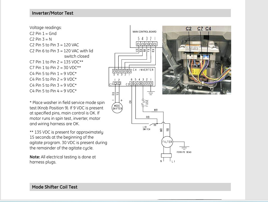

The C7 1 & 2 test pin locations for the mode shifter 135v AC for 15 seconds then 35v AC

Sorry DC voltage for the pin out tests

Jeffrey, I recognized that latest table you posted so I reread my notes above and it looks like I DID do that test before, though it wasn’t very precise since I was just trying to keep the probes touched to the posts on the connector on the motor. But this time (see photo below) I got a bit more sophisticated and more solidly connected. I hooked up the original mode shifter and put safety pins through the wires that I could attach my probes to. As soon as I plugged the washer into the wall, immediately it measured 290 volts. You’ll see in the photo that I had the polarity backwards, but for this purpose it doesn’t matter… just subtract the minus sign. Then I put the washer into field test mode and moved through the various positions to AL and AH. The measured voltage never changed except by maybe momentarily by a volt or two one way or the other as test positions changed. It never dropped to 135 VDC or 30 VDC, even after 60sec. The only time the voltage dropped was when I unplugged the washer from the wall. It acted like there’s a capacitor in there somewhere. The voltage dropped gradually from 290 VDC down to 0 VDC over the course of probably 2-3min, beginning rapidly and then slowing down the closer it got to 0 VDC. I don’t know if these results are expected. I’m just reporting.

It really sounds as if there is an issue with the motor control. Yor extremely high voltage reading and no change in voltage during mode changes are the biggest indicators

Is it possible to replace only the motor control? or would the only option at this point be to replace the entire $350 motor assembly?

The GE WH20X10058 is not sold as a separate, standalone inverter board. It is manufactured and sold strictly as an integrated drive motor and electronic inverter assembly

Thank you Jeffrey. Then I guess I’m at the end of the line and it’s time to buy a new washer. Thanks again for all your help with this project! I totally appreciate it!